Hi,
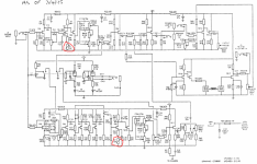
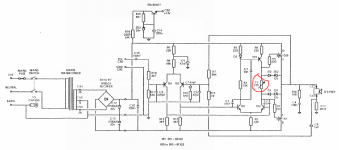
A guitarist friend of mine owns one of these amplifiers and he managed to twiddle every bias pot in it and now "it just doesn't sound right". I had a look at it for him but I can't figure out how on earth to set any of the biases, even the power stage which I thought looked pretty simple. I can bias a valve amp easily enough but am confused as to how this SS amp even works at all. I'm sure it's pretty simple and straight forward but I am totally clueless. Could someone offer some pointers as to what resistor(s) I should be measuring across and what the voltage ranges should be? The schematics for pre and power sections are attached with the bias pots circled in red.
Thank you
Attachments
Last edited:
First, slap his hand with a steel ruler .... hard.
If he burns those original MosFets he'll have to pay a lot for replacements .... with a high probability of receiving fakes.
Back to the schematics.
The first one is the preamp, the presets are to get reasonable symmetry in those FET stages.
a) measure what voltage you have on the top end of R7, I expect around 25V there.
Then measure what you have on the bottom end, a.k.a. TP1 , and set P1 so you have "1/2 of whatever you measured before + 1V" there.
When I say "top" or "bottom" means "as seen on the schematic", in the actual PCB it may point anywhere, follow traces to know where it's connected to.
b) same as before, set P2 so you get TP2 to 1/2 of what you measure on "the other end" of R42 + 1V .
That said, this doesn't change *sound* that much, your friend is simply being paranoid , that's why he touched those presets in the first place. He shouldn't.
c) now we are getting into a minefield.
In the Power Amp, P1 is the output transistors bias pot.
You set it too low, the amp has crossover distortion which is horrible: buzzy, **kills sustain**, choppy, farty, etc. Ugh.
You set it too high: the amp overheats and may burn.
To boot, in this particular amp there are no "emitter"/source/"cathode" resistors across which measure bias current, so you'll have to add your own temporarily.
Have a careful look at the PCB traces and wiring, Trace Elliott *should* have provided some way of interrupting the tracks or current path to measure at the factory.
Follow the path: how does 1058 drain leg get the +V voltage (around 50 to 60V).
I don't remember that particular one details, although I have repaired quite a few of the TE family.
Is there a wire there? A PCB track? There *should* be some way of interrupting that path, either by desoldering a wire end or sometimes tracks *are* interrupted somewhere (on purpose) so you can connect an ammeter in the path and then jump it with a jumper or simply a drop of solder.
Same on the V- connection to 162 Drain.
Either of them would be the same for measuring purposes.
Follow the paths and post a clean well illuminated picture so I can detect that possible jumper or tell you where to create one by cutting a trace.
Good luck.
WOW thank you so much for the detailed reply!!! The amp was being used at a gig last night (in its mis-biased state) but is free for a few days so I will have a look at it again ASAP. I remember seeing a large wire jumper on the board with the power amp and power supply so hopefully that might be all that needs to be removed/replaced. I will post a photo when I have it sorted.
Again, thank you so much for explaining the process so well.
Again, thank you so much for explaining the process so well.
Tramp (non Super Tramp) Power Amp 47uf and 220uf
Received Tramp butchered by lame repairists, need to obtain clarification if schematic has glitches and or lame repairists booboo'd.
on poweramp pcb silkscreen capacitors labels C1 and C2, 220 and 47 per drawing, were NEVER replaced visualled solder landings untouched.
These are 50V 220 and 220.
Obviously C2 radial lead spacing is smaller than C1 as visualled on the pcb.
Should I return C2 from factory 220 (drawing says 47 for C2)?
Or just leave C2 as 220 regardless of drawing disparity?
Thanks in advance.
btw, can i flex wire the sip 9 pin so vibrations dont kill the tda1514 integral legs?
this adds about 3 to 4 inches of flex wiring to each leg (crosstalk? current impact?) mounting the ic on the opposite side of the original mount plane.
the mounts are not accomodating of vibrations that will kill the legs (metal fatigue)
First, slap his hand with a steel ruler .... hard.
If he burns those original MosFets he'll have to pay a lot for replacements .... with a high probability of receiving fakes.
Back to the schematics.
The first one is the preamp, the presets are to get reasonable symmetry in those FET stages.
a) measure what voltage you have on the top end of R7, I expect around 25V there.
Then measure what you have on the bottom end, a.k.a. TP1 , and set P1 so you have "1/2 of whatever you measured before + 1V" there.
When I say "top" or "bottom" means "as seen on the schematic", in the actual PCB it may point anywhere, follow traces to know where it's connected to.
b) same as before, set P2 so you get TP2 to 1/2 of what you measure on "the other end" of R42 + 1V .
That said, this doesn't change *sound* that much, your friend is simply being paranoid , that's why he touched those presets in the first place. He shouldn't.
c) now we are getting into a minefield.
In the Power Amp, P1 is the output transistors bias pot.
You set it too low, the amp has crossover distortion which is horrible: buzzy, **kills sustain**, choppy, farty, etc. Ugh.
You set it too high: the amp overheats and may burn.
To boot, in this particular amp there are no "emitter"/source/"cathode" resistors across which measure bias current, so you'll have to add your own temporarily.
Have a careful look at the PCB traces and wiring, Trace Elliott *should* have provided some way of interrupting the tracks or current path to measure at the factory.
Follow the path: how does 1058 drain leg get the +V voltage (around 50 to 60V).
I don't remember that particular one details, although I have repaired quite a few of the TE family.
Is there a wire there? A PCB track? There *should* be some way of interrupting that path, either by desoldering a wire end or sometimes tracks *are* interrupted somewhere (on purpose) so you can connect an ammeter in the path and then jump it with a jumper or simply a drop of solder.
Same on the V- connection to 162 Drain.
Either of them would be the same for measuring purposes.
Follow the paths and post a clean well illuminated picture so I can detect that possible jumper or tell you where to create one by cutting a trace.
Good luck.
- Status
- Not open for further replies.