Hi! I want to adjust the bias of a SS amp from the 70. I have experience with low voltage electronics circuits. Guitar/bass pedals and such where you usually do not need to measure current, just voltage.
I've attached the schematic of the power amp and the instructions to set the bias. The instructions are pretty straightforward but I don't know where to put the multimeter terminals to measure the current. That's the main problem. Also I don't know if I should remove the fuse in order to set the bias.
I know it's too basic and stupid but can't find a safe answer.
Thanks!
Attachments
Last edited:
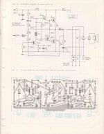
First measurement - bias, measure across R36 the 0.47r reisitor (1 dmm lead connected to each side of the resistor), then adjust R34 to get 33mV across that resistor.
Next take your red lead and place on the positive side of C21 (marked in blue as “1”) then the black lead to the chassis and adjust R24 until you have 12.5Vdc.
Please be careful there are fairly high voltages right around there and a slip of your dmm could mean costly repairs.
Next take your red lead and place on the positive side of C21 (marked in blue as “1”) then the black lead to the chassis and adjust R24 until you have 12.5Vdc.
Please be careful there are fairly high voltages right around there and a slip of your dmm could mean costly repairs.
What he mans is that you measure the current by measuring the voltage across the resistor. Knowing the voltage across it and the resistance value gives you the current, courtesy Mr. Ohm. I = V / R .
Jan
Jan
Hi. Thank you very much!
About the first measurement. I see, using ohm's law. The problem is that this old resistors could be a little off. My tester reads between 0.6r and 0.7r...It's not the best tester in the world though. But that small difference means a lot when doing the maths.
Is there a way to directly measure the current so the resistor tolerance can't be an issue?
As for the second measurement, got it!
edit: the resistor value is so low that the tester is not reliable enough, so a current measure would be ideal
Last edited:
You dmm probably has high resistance leads - touch them together and take that number away from your resister measurement.
Use the 33mV, which across a 0.47r resistor will give you the 70mA current.
Does not make any difference the value you measure on that resistor you are measuring voltage and in turn current using ohms law and math.
Use the 33mV, which across a 0.47r resistor will give you the 70mA current.
Does not make any difference the value you measure on that resistor you are measuring voltage and in turn current using ohms law and math.
Is there a way to directly measure the current so the resistor tolerance can't be an issue?
Dependent on your skill level, you could open one side of the resistor and place your DMM (in current mode) in series with the resistor. That will give you an accurate measurement but involves breaking into the circuit.
This is a better option:
You dmm probably has high resistance leads - touch them together and take that number away from your resister measurement.
Use the 33mV, which across a 0.47r resistor will give you the 70mA current.
Does not make any difference the value you measure on that resistor you are measuring voltage and in turn current using ohms law and math.
If the R36 resistor is an accurate one, then everything is fine. But if it is real value is, let say 590R, then the calculated current would be quite off. The problem is my meter not being accurate enough. For these low resistor values my meter says 0.6 or 0.7, but nothing in between. Therefore I can't also get the exact resistance between leads
I can proceed as avtech23 says without problem but I would be a real PITA for this board. I would have to desolder and resolder lots of wires after doing the setting.
Let's think the R36 resistor is an accurate one!
Thank you 🙂
I can proceed as avtech23 says without problem but I would be a real PITA for this board. I would have to desolder and resolder lots of wires after doing the setting.
Let's think the R36 resistor is an accurate one!
Thank you 🙂
Did you calibrate your leads like I said? Touch them together and measure the ohms, probably 0.2-0.4, them measure your resistor and subtract that value from your reading. Measure 0.8 - 0.4 and you got 0.4r.
You could always start low - say 20mV and see how hot the heatsinks get and adjust upwards if it stays reasonable after 20-30 mins. You just don’t want to start too high and have it run-away and blow something. 33mV is a pretty safe level giving 70mA, I wouldn’t think you would have any problems until 150mA+, at least nothing you couldn’t tell was getting quite hot.
You could always start low - say 20mV and see how hot the heatsinks get and adjust upwards if it stays reasonable after 20-30 mins. You just don’t want to start too high and have it run-away and blow something. 33mV is a pretty safe level giving 70mA, I wouldn’t think you would have any problems until 150mA+, at least nothing you couldn’t tell was getting quite hot.
I am QUITE CERTAIN (coming from that era and having built dozens of such amps) that instructions mean *actually* measuring current.
In this particular amp you remove 1 Amp fuse (M1) from its holder and measure current between holder terminals.
Old PCBs went so far as to have an interrupted supply track, either with one pad at each half (both pads being side by side) which after adjustment would have been joined by a piece of wire, or 2 D shaped pads almost touching each other by the flat side (imagine a round pad vertically split in the middle) which after adjustment would be joined by a drop of solder.
Anybody mind if I put in my 3 cents here...
This is an OLD amplifier, nothing is going to test or measure exactly on spec. Testing current on the fuse would have worked well enough in 1975 but with component aging and everything else it's been through, it's likely that all the bias points are a little off.
So the goal is to get the output to sit at 1/2 the supply voltage and for the bias to put just a tiny trickle of current through the outputs. It's unlikely you'll get it much better than that.
Follow the procedure like this...
First with the amplifier turned off ... clean those trimmer pots with a bit of contact cleaner or rubbing alcohol and turn them gently back and forth end to end a few times. Then put them back in their starting positions and allow them to dry.
Next power up the amplifier with no input and no speakers.
Volume control at 0.
Now measure the power supply... from ground to M1 (the fuse)
Divide by 2. (eg. 24.6 /2 == 12.3)
Now adjust R29 to get the bottom of R36 as close to the 1/2 rail voltage as you can.
Next the bias current...
The spec says 80 ma, for the whole amplifier. The previous stages probably idle at about 20 or so on their own... so we do some more math. For an overall idle current of 80ma, we want roughtly 60ma through R36. We don't actually care what the value of the resistor is because with components this old it's likely to be a bit off anyway. So we assume 0.47 ... Ohms law says E = I X R so... .060 X .47 == .028 volts or 28mv.
Now adjust R34 for as close to 28mv across R36 as you can get.
Let things settle for a few minutes.
Now recheck your centre supply voltage and the voltage across that resistor. Go back and forth a couple of times getting it as close as you can.
Now comes the acid test ... hook up a source and speaker... with music playing as quietly as possible... so quiet you have to put your ear right up to the speaker... you should not hear any distortion. If you achieve this, the job is done.
Final check ... make sure nothing is getting hot.
Last edited:
I see...so would be safe to measure current between fuse holders? Once it is removed, of course. I don't know if if there's something I have to worry/take into account about JMFahey's second paragraph...but thanks.
Thank you Douglas Blake and bullittstang, I really appreciate your help. I'm learning a lot 🙂
I've recaped the whole circuit. Only electrolytics, they were quite off. Some of them doubled their value.
Cheers!
Thank you Douglas Blake and bullittstang, I really appreciate your help. I'm learning a lot 🙂
I've recaped the whole circuit. Only electrolytics, they were quite off. Some of them doubled their value.
Cheers!
"Doubled their measured value" actually means high leakage . Ugh.
As of pulling a fuse and measuring, is as valid today as 50 years ago 🙂
My "second paragraph" refers to a trick used way back then (and still valid of course) incorporated into PCB designs, but having a fuse holder does the same.
As of pulling a fuse and measuring, is as valid today as 50 years ago 🙂
My "second paragraph" refers to a trick used way back then (and still valid of course) incorporated into PCB designs, but having a fuse holder does the same.
I see...so would be safe to measure current between fuse holders? Once it is removed, of course. I don't know if if there's something I have to worry/take into account about JMFahey's second paragraph...but thanks.
If you want to try the fuse method, no problem.
But, if you follow the schematic, you will note that fuse is not isolated to feeding only the output transistors. It appears to be feeding at least one channel, possibly the entire amplifier. There's likely to be a lot more than 80ma going through there.
The concern is that something is shorted and when you turn the amp on it ends up blowing out the current scale on your meter. (It's not common, but it does happen)
If the R36 resistor is an accurate one, then everything is fine. But if it is real value is, let say 590R, then the calculated current would be quite off. The problem is my meter not being accurate enough. For these low resistor values my meter says 0.6 or 0.7, but nothing in between. Therefore I can't also get the exact resistance between leads
I can proceed as avtech23 says without problem but I would be a real PITA for this board. I would have to desolder and resolder lots of wires after doing the setting.
Let's think the R36 resistor is an accurate one!
Thank you 🙂
Why not just measure R36? Your DMM must have an ohms setting.
Jan
WhatEVER the value of R36 is, adjust for 30mV.
This works if designed with 0.1r or 33r here (different load impedances).
It's not a high-class amp. There's no magic bias.
In fact you "could" trim by feel. The heatsink should be mildly warm and not hot after 10 minutes. But you have to sneak up on it. If you mistakenly start at 1 Amp it may burn-up before you know it.
- Home
- Amplifiers
- Solid State
- Biasing SS amp. Measure current with tester