Hello all. I’ve been lurking on here for a while now, but this is my first posting. I’m a fairly recent convert to valve/tube amps, and I’m trying to get to grips with the characteristics of different valve types and the mysteries of biasing etc. Although I covered basic electronics as part of my maths and physics studies, that was over forty years ago, so please forgive me if I seem a bit clueless!
My current amp is a Jadis Orchestra. It’s a simple integrated push-pull amp using ECC83s and EL34s. According to the spec it operates in Class A/B and is rated at 40 watts output. The amp has manual (fixed) bias and according to Jadis can also be used with KT88s, KT90s, 6550s, and 6CA7s.
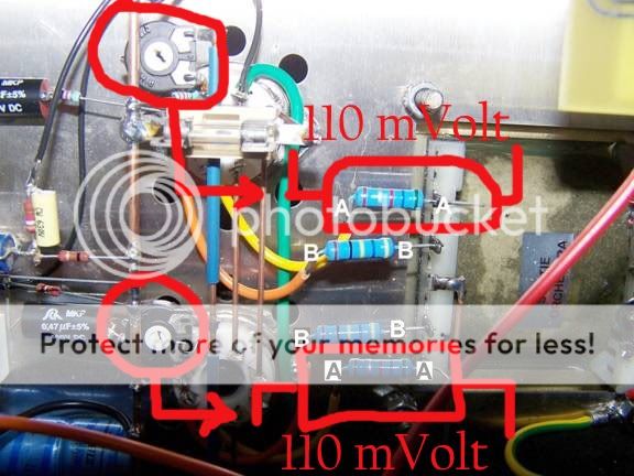
Jadis have advised me that the correct bias, using matched tubes, is set by measuring the voltage drop across the R5.62 resistor between the anode/plate and the output transformer and adjusting the bias pots to achieve a voltage drop of between 90 and 120 mV, with 110mV (=19.6mA) being ideal. See attached image.
According to Jadis, the same figures apply whether you are using KT88s, 6550s or 6CA7s. With KT90s they recommend going up to 120mV.
I’ve used these figures when re-valving with EL34s with no problems, and the amp sounds fine. However, I’m curious to know how this method of biasing relates to the figures I’ve seen for EL34s which suggest that the cathode current should be between 50mA and 30mA, depending on plate voltage.
Also, as different cathode figures apply to other valve types, how can a single figure apply to the anode measurements, pretty much regardless of valve types?
Any advice, explanations would be gratefully received.
My current amp is a Jadis Orchestra. It’s a simple integrated push-pull amp using ECC83s and EL34s. According to the spec it operates in Class A/B and is rated at 40 watts output. The amp has manual (fixed) bias and according to Jadis can also be used with KT88s, KT90s, 6550s, and 6CA7s.
Jadis have advised me that the correct bias, using matched tubes, is set by measuring the voltage drop across the R5.62 resistor between the anode/plate and the output transformer and adjusting the bias pots to achieve a voltage drop of between 90 and 120 mV, with 110mV (=19.6mA) being ideal. See attached image.
According to Jadis, the same figures apply whether you are using KT88s, 6550s or 6CA7s. With KT90s they recommend going up to 120mV.
I’ve used these figures when re-valving with EL34s with no problems, and the amp sounds fine. However, I’m curious to know how this method of biasing relates to the figures I’ve seen for EL34s which suggest that the cathode current should be between 50mA and 30mA, depending on plate voltage.
Also, as different cathode figures apply to other valve types, how can a single figure apply to the anode measurements, pretty much regardless of valve types?
Any advice, explanations would be gratefully received.
Hi,
You have to remember that all tubes will be slightly different in gain etc.
Even a matched set will be very slightly off. So the amount of negative voltage applied to the grid to turn the tube "off/down" will be slightly different with each EL34 to get the same standing " idle" current. The idea that the "current<<not bias voltage" would be the same for different tubes is because if the load resistance is the same (only the tube has changed) then with simple ohms law the voltage drop across it or load will be the same with the same current the tube type is irrelevant. However the amount of bias required to turn "off/down" the tube may be higher or lower. In some cases (wrong tube type) you may not have enough negative voltage to turn down the idle current enough and the tube /op Tx will (over heat).
Hope this helps
Regards
M. Gregg
Jadisman: Can you confirm the value of the R that you are measuring across? 20ma seems very light for idle current for any of the tubes listed. What is the 3rd color band on the R? The green and blue (for 5,6) are pretty clear. Are you sure that those resistors are between the plate and the transformer and not on the cathode? If the resistors are on the plate side they are at high voltage so be careful when measuring. If they are on the cathode they are at much lower voltage.
If you can carefully measure the voltage from either side of those resistors to ground that would tell you what side of the tube they are on, and if they are on the plates, it will give you an indication of the B+ voltage on the tubes.
Running KT88's at the same B+ and idle current as EL34's would have them loafing along.....
Many amps have the measuring resistors shared between pairs of tubes (on the cathodes). Since this appears to be a PP amp, do you have 4 sets of R's and pots or two sets of R's and pots? If you only have two sets, they are most likely on the cathodes.
On other (maybe obvious) thing........ EL34's and 6CA7's are pretty much the same tube as far as power dissipation and idle current, etc, and 6550's are light versions of KT88's.
Thanks for the replies "M Gegg" and "boywonder"
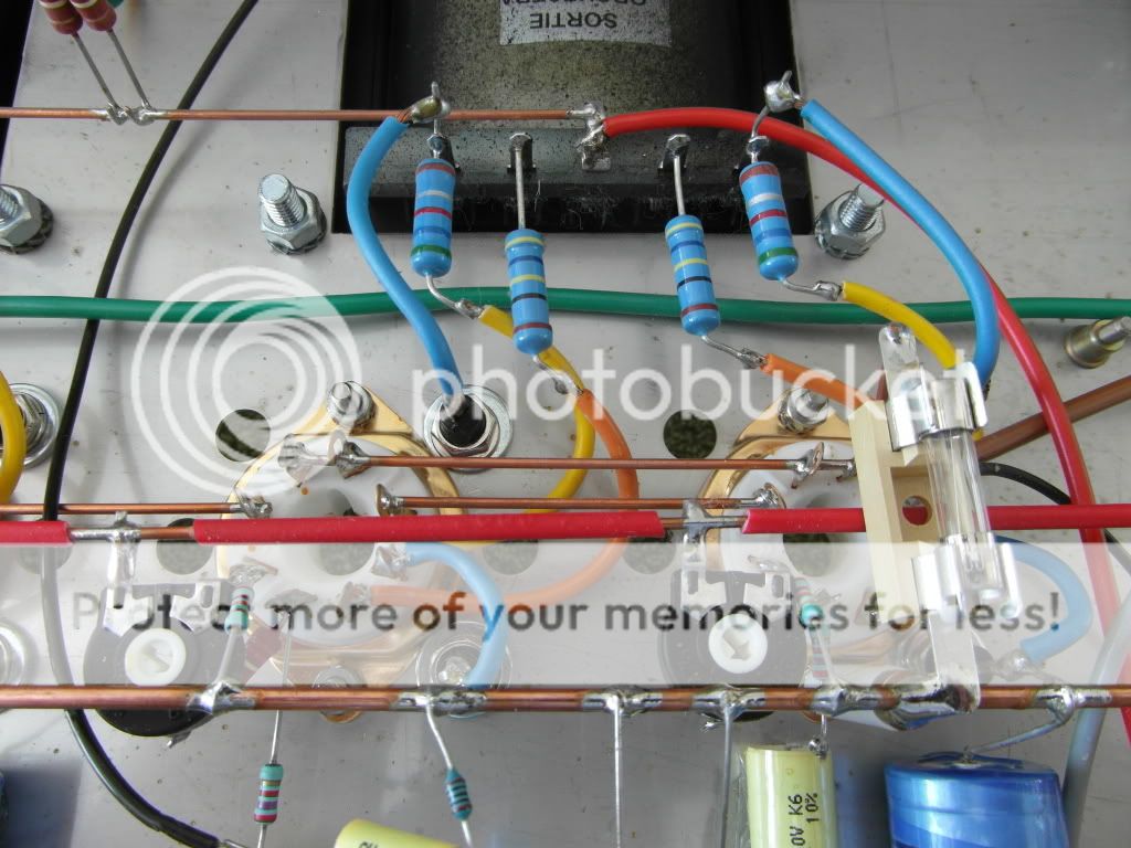
Boywonder: See attached image, which I hope is a bit clearer . This shows one pair of tube sockets. The other pair are identical. The resistor I'm talking about is the one between the yellow wire on pin 3 and the output tranformer. The blue wires connect to external test probe sockets which are used to measure the voltage drop. The bias pots are adjusted with a plastic screw driver inserted through the ventilation hole directly above.
Boywonder: See attached image, which I hope is a bit clearer . This shows one pair of tube sockets. The other pair are identical. The resistor I'm talking about is the one between the yellow wire on pin 3 and the output tranformer. The blue wires connect to external test probe sockets which are used to measure the voltage drop. The bias pots are adjusted with a plastic screw driver inserted through the ventilation hole directly above.
An externally hosted image should be here but it was not working when we last tested it.
Does the Jadis run them deeper into Class B? If so, the quiescent current will be smaller and the average current will increase more when signal is present. 40W from a pair of EL34 is consistent with running nearer to Class B.
I agree, and further the measurement resistors appear to be in the plate circuit, so high voltages on the order of 450V or more are certainly present. Use extreme caution when making these measurements!

Can't say I am the least bit thrilled to see how Jadis put this amp together.. Make sure when you have been in there that you have not disturbed any components so that an arc to another part or the chassis is possible.
Also welcome to the forum!

I totally agree. High voltage buss line left uninsulated, and resistors left suspended in the air on wires. Output tube filaments in series? When will those fools learn?Can't say I am the least bit thrilled to see how Jadis put this amp together..
Anyway, welcome to the forum!
Last edited:
Jadisman it is only a matter of time until we persuade you to build one of your own!
I serviced Jadis gear in another life and always wondered what drummer they were marching to.. No one designs like Jadis, although plenty build that way. Somehow they still manage to sound good. Some of the older designs were a nightmare to repair.
Just make sure you use output tubes from the same lot and manufacturer - do not mix since the filaments are in series. In fact when you buy your next set it would be good to mention this to the vendor in the hopes that they can at least verify that the cold resistance of the filaments are the same, better still would be if they measured the filament current at the nominal filament voltage. (Not at all likely that they will.) These tubes were not intended for series string operation, so the voltages may not divide evenly across them resulting in some running hotter than others - those ones are likely to burn out their filament first (normally rare in these tube types) causing the entire amplifier to quit.
Kevinkir, thanks, this is very useful and helpfull advice and I will certainly bear it in mind when I buy my next lot of tubes.
You are absolutely right about the sound of the Jadis. Despite its apparent shortcomings constructionwise, it sounds lovely.
As for building my own amp, I'm currently ooking around for a suitable valve/kit as a winter project. In the meantime I'm restoring an old Quad 33/303 set up.
You are absolutely right about the sound of the Jadis. Despite its apparent shortcomings constructionwise, it sounds lovely.
As for building my own amp, I'm currently ooking around for a suitable valve/kit as a winter project. In the meantime I'm restoring an old Quad 33/303 set up.
I've seen a number of modern tube amps with very low bias currents and higher B+ voltages.
The VTL 100 monoblocks, for example, only had 25mA of bias through each EL34.
Compare that to my vintage Eico HF-60s which had 50-60mA, depending how much you hated your output tubes.
The VTL 100 monoblocks, for example, only had 25mA of bias through each EL34.
Compare that to my vintage Eico HF-60s which had 50-60mA, depending how much you hated your output tubes.
Two consideration:
- the terrific method used to check the bias: two test point with an high voltage present on them, take maximum care
- the cabling is very dangerous.
After this the quiescent current for a EL 34 would be about 30 mA and for KT88 can be up to 40 mA.
The fuse, for security in inserted on both cathode circuit but would be better to put one for each tube.
In my opinion a little mod can be: take off the anode resistor for bias check, connect the cable directly to opt trafo; put a 1 ohm /1w resistor on each cathode to ground to read the right current so them also figured as fuse
Walter
The quiescent current for a valve power amplifier depends on the design of the stage, not just the valve. The design of the stage includes the supply rail voltage and the OPT impedance and how far into Class B it goes. 20mA could be right for EL34 in one design, while 60mA could be right for EL34 in another design. You also need to be careful when comparing cathode currents in most designs with anode currents in this design.
In every case on a push pull AB1 amp the 30 mA (+/- 5mA) is the minimum bias to set to avoid crosstalk distortion, indipendently from power tube (classic types) .
In case of tube with more Pa up to 40 mA can be a good choice to have some little power in class A.
And this in not related from opt trafo specs.
Walter
In case of tube with more Pa up to 40 mA can be a good choice to have some little power in class A.
And this in not related from opt trafo specs.
Walter
I would say 20 mA is unusually low for a EL34 based class AB1 PP amp, whatever the design of the stage is, but is not an error and has been confirmed by Jadis. I suspect that Jadis "designers" (I would not call them "engineers") decided to run their tubes at reduced plate dissipation to avoid premature tube failures and service returns, problems who plagued all their (true class A) cathode resistor biased amps.
As far as wiring and safety issues were concerned, everything has been already said: it's just terrible. I'm still wondering how they got the (very stringent) European C.E electrical conformity label license.
As far as wiring and safety issues were concerned, everything has been already said: it's just terrible. I'm still wondering how they got the (very stringent) European C.E electrical conformity label license.
Last edited:
I'm still wondering how they got the (very stringent) European C.E electrical conformity label license.
They did not "get" that licence; they just put the label on the chassis as most manufacturers do
.See how many tube amps are around, for esthetical reasons, without covers to protect the hot parts from the outside world; in fact authorities do not check if these safety norms are followed
That really depends on what operating point had been chosen by the designers and what additional measures may have been taken against crossover distortion. The limiting factor is how much power can be dissipated safely. In the case of this amp, the EL34s appear to be operating at or above 525V, so 30mA (15.75W) looks somewhat on the warm side for a 25W rated tube.In every case on a push pull AB1 amp the 30 mA (+/- 5mA) is the minimum bias to set to avoid crosstalk distortion, indipendently from power tube (classic types) .
Sent from my LG G2 with CM13 using Tapatalk
Last edited:
- Status
- This old topic is closed. If you want to reopen this topic, contact a moderator using the "Report Post" button.
- Home
- Amplifiers
- Tubes / Valves
- Biasing a Jadis Orchestra