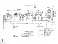
I'm resurrecting an old Heathkit A8-A amp (see attached schematic) and I have a question about plate current in the two 6L6Gs (which I believe to be original 50s vintage; original spec is 6L6 or 6L6G). It has been completely recapped and all out-of-spec resistors have been replaced.
Plate voltage on the 6L6Gs is 392V; cathode voltage is 26.7V. As measured across the output transformer, the plate current is 53 mA on one tube (8V, 150Ω winding) and 47 mA on the other (7.7V, 165Ω winding). The 10W cathode resistor measures at 254Ω. Measured current across this resistor is 105 mA (26.7V/254Ω), or 52.5 mA per tube.
As I understand it, the recommended bias point for an AB amp is 70% of rated power (I=.7(P/V), or .7(19/392)), which would be ~34mA. If that's correct, the observed measurements seem high.
Questions:
- Do I understand this correctly? Is the plate current higher than optimal?
- Assuming the current is higher than you'd like, what's the best way to lower it? It seems to be a choice between lowering the plate voltage (adding an inline resistor) or bumping the cathode resistor to a higher value.
- If I switch to a pair of 6L6GC tubes (rated at 30W), would that bring things back into spec? If everything else stays the same, that would put the 70% point at 54 mA, which is very close to where it is now.
Answers? Questions? Comments? Insults?
Thanks.
Attachments
Last edited:
Chances are, your '50s vintage amplifier was made to work with a power mains voltage of either 110VAC, or 115VAC.
If you have 117V, 120V, or 123V power mains, all the amplifier voltages will be high, and all the tube currents will be high.
You can check the 6.3V filament voltage, and see what you get.
You can build a Buck transformer, depending on your power mains voltage, and the original spec for the amplifier power voltage, you might need either a 6.3V buck transformer or a 12.6V buck transformer.
As always, when the output tubes have common bias (in this case the 250 Ohm self bias resistor), I highly recommend that you use very well matched output tubes.
Push Pull output transformers do not like unmatched plate currents, they saturate too early.
That amplifier uses global negative feedback. Global negative feedback does not fix early saturation.
....Is the plate current higher than optimal?...
What is "optimal"? Best life? Best heat in winter? Lowest THD?
This is a class A amp (essentially), NOT an over-volted AB guitar amp. You can run 100% of the number in the book. For early 6L6 types, that was 19W if you did not measure, 21W if you did.
You are at 18W-19W. There is certainly no immediate problem.
I don't disagree with 6A3 that line voltages are gone up since some of use were younger. A 10% drop with a 12V 1A transformer may be good to get some time.
I believe you could also buck at the B+ secondary center tap, if the only extra transformer you have to try is higher than 6 or 12V on its secondary.
Is the "death cap" shown in the schematic still in place? I suppose it wouldnt be if you've already replaced the original AC cord with a grounded 3 prong ;')
Is the "death cap" shown in the schematic still in place? I suppose it wouldnt be if you've already replaced the original AC cord with a grounded 3 prong ;')
Thanks for the replies.
Measurements were taken running off a Variac at 117V. Filament voltage was 6.3V. Filament for the 5U4G was 4.9V. At 125V, they're 6.75V and 5.25V, respectively.
We have PG&E here, so power is variable and unreliable. Tonight we have 120V at the outlet. 😉 Given the unpredictability of the supply, might a regulated PS be a better solution than a simple buck transformer? I'm thinking that a fixed 10% drop in conjunction with a voltage dip at the wall would leave me with between 100 and 105 V at the input, and associated low voltages throughout.
Yes, a pair of matched tubes is on the list, once I get everything else sorted.
One other thing: the green/yellow wire from the power transformer has been cut between the transformer and point Y (it was rerouted to an added external plug). I measure 27V between that wire and the chassis. Point Y is the chassis (through the shield on input P). Is there any reason not to splice that wire back together per the schematic?
No, the death cap is not there. Nor is a 3-prong power cord. It is currently wired with the fuse on one leg and the switch on the other. This, too, shall change. 😉 Current intention is to install a polarized plug, then put the fuse and switch (in that order) on the hot leg, connecting neutral directly to the transformer. I'd like to install a 3-prong, but understand that it's not always feasible to do so on some of these older amps. If all I have to do is connect the ground wire to the chassis and wire the hot and neutral as described earlier, I'm in.
Last edited:
Utility power in the old days was much more erratic than most folks' power today. The power quality rarely depends on the "brand" on the bill. Last time I had a PSE&G it was steady 121V. Here the "brand" has changed 3 times in 5 years but the power stays the same: STEADY 125V at the street, 124V-109V in the house depending how I strain (my!) feeder. The unpredictable voltage in the old days is part of why the Design Center rating system was promoted: it gave wide leeway for supply variance.
Yeah, all you have to do is install a 3-wire AC cord and "connect the ground wire to the chassis and wire the hot and neutral as described earlier". It's one of the few mods on a vintage amp that I would think does not "molest" its vintage aspect.
The green-yellow wire oft went to chassis as well; perhaps someone cut it trying to chase down a humm problem. It's supposed to keep the heater windings "balanced" about the chassis, though in this design it goes to a strange place - "Y" - to me. Another way they did this was with a potentiometer across the heater winding, its wiper to chassis.
I'd try connecting it to chassis, see if it makes a difference vs floating. That's how it would be wired originally, with the input shorted - the typical test condition for residual noise.
As I understand it, the recommended bias point for an AB amp is 70% of rated power (I=.7(P/V), or .7(19/392)), which would be ~34mA. If that's correct, the observed measurements seem high.
Questions:
- Do I understand this correctly? Is the plate current higher than optimal?
First, don't try to second guess the designers of the amp for its operating point. Since your schematic has no voltages to go by then you should just check the values of the resistors to see if they are within acceptable specs. Then set the variac to 117v and see if that gives 6.3v heater, (you have, it's good). Then take the 6L6 plate voltage and subtract the cathode voltage for your plate dissipation formula. Use the cathode voltage and resistance to get the cathode current. That's the total current through the outputs and becomes a good conservative number to use since it also has the screen current included. Then understand the plate dissipation your amp has (having two good tubes) is designed against a load line which takes the drive signal swing into consideration to get the SIGNAL POWER out of the amp. So the biasing voltage in an AB amp could be just short of full class A, or it could be biased cold and be very close to class B. So the 70% AB power point you speak of is not "optimal" except in a general way if your drive signal swing gets the signal power you want to see into the speakers. Your amp will have its own point if all the components are within spec and your line voltage is at 117v.
Utility power in the old days was much more erratic than most folks' power today. The power quality rarely depends on the "brand" on the bill. Last time I had a PSE&G it was steady 121V.
You apparently don't live in rural California. 😉 Power is all over the place. Delivery itself is unreliable; that's why everyone has backup generators. Even with energized lines, voltage varies. For those of us who use sensitive equipment (e.g. for long-range internet access), those variations can be crippling.
Thanks for all the help. 3-prong plug is installed, center tap is connected. Let's see how well this now works on a guitar. 😀
Don't laugh. I used this amp years ago to power an FM tuner in my high school bedroom. After that, I built a cab and used it as a guitar amp. Seemed to work well at the time, but maybe that was just youthful exuberance. I'm not dumb enough to fire it up again with wax caps and what not, but I'm thinking that a little old school breakup might fit the bill for garage rock.
We shall see.
- Home
- Amplifiers
- Tubes / Valves
- Biasing a Heathkit A8-A (6L6) amp