And don't forget a gate stopper resistor, 220 ohms or so, attached physically right at the gate.
That said, this is still a much more complicated circuit than you need.
That said, this is still a much more complicated circuit than you need.
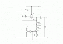
Put the 220 ohm resistor directly to the gate. The bypass cap goes to the other side of it. The grid resistance (pot in this case) ties back to the FET drain, not the top of the LED string. Cross your fingers that the biasing gives you the proper current.
Regulation is probably not important- this is a class A circuit. But the rails should be reasonably quiet, and that means thorough bypassing.
A much simpler solution is using a negative rail for the cathode return as I mentioned before, losing the current source.
Regulation is probably not important- this is a class A circuit. But the rails should be reasonably quiet, and that means thorough bypassing.
A much simpler solution is using a negative rail for the cathode return as I mentioned before, losing the current source.
I'm afraid that's not going to work.
Your volume control pot must go down to ground. As you have it, not only would it pass DC onto all your sources, but it would be unable to attenuate.
You don't need to use LEDs (unless you like their cheery glow).
I have exerted my very fullest draughting efforts...
Your volume control pot must go down to ground. As you have it, not only would it pass DC onto all your sources, but it would be unable to attenuate.
You don't need to use LEDs (unless you like their cheery glow).
I have exerted my very fullest draughting efforts...
Attachments
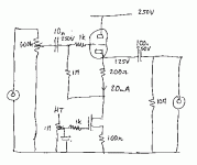
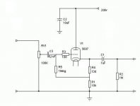
It would be even better if the range of voltages to the gate of the FET was restricted to a maximum of +5V (4V usually turns on an enhancement FET). Replace the 1M pot with a 10k pot and take a 390k resistor up to the +250V. Then add a 1M series resistor between the pot's wiper and the 1k gate stopper resistor.
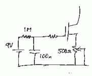
Alternatively, you could use a 9V lithium battery on the gate and fit a 500 Ohm variable resistor in the source circuit of the FET instead of the fixed 100 Ohm. The battery would not need a switch.
Alternatively, you could use a 9V lithium battery on the gate and fit a 500 Ohm variable resistor in the source circuit of the FET instead of the fixed 100 Ohm. The battery would not need a switch.
Attachments
Hi,
Why go trough all the trouble? Why dont simply use a ordinary resitance coupled follower with say 100V cathode and ground.
Just replace the CCS in the circuit posted earlier with a resistor of 5kohm, (if you want to keep current at 20mA). So then the circuit will be 5kohm and 200ohm resistors in series from ground, the gridresistor connected to the connection point between the resistors, (just replace the CCS in the circuit previously posted by EC8010)
The performance difference between this simple circuit and a CCS based circuit is not possible to notice as long as the output voltage is reasonable, only for very high voltage swing you can see any differences, an added advantage is that you dont need to contaminate the tube circuit with SS circuitry and the circuit will be very simple.
I have built and measured CF's using this method and CCS using SS or tube circuits and it is actually very difficult to measure any differences. However the diffrence between a CF using only the cathode bias resistor as the one you posted in your first post and a dual resistor or CF based on is stunning.
Hans
Let me put it this way. All the buffer needs to do is sound better than a Parasound PHP 850 which is based on opamps. If the standard output of a CD player is 2v peak to peak and the grid is biased at -6 volts, which in turn means the cathode ia at +6 volts, then there should never be any negative clipping. Right?
All it has to do...
The standard output of a CD player is 2VRMS which is 5.6Vpk-pk.
If you bias the cathode to +125V with a resistor, it will be pretty linear. If you bias it to +125V with a CCS load, it will be very linear. If you bias it to +6V with a CCS (and ground the grid) it might just be able to swing 2VRMS cleanly (the CCS uses up swing, you see). If you ground the grid and try to use resistor bias on the cathode it will be terrible.
The fellows who design op-amps are amongst the world's very best electronic design engineers, so making something better is not trivial...
There is more to linearity than merely avoiding clipping.
Re: All it has to do...
Thanks for correcting me EC8010. Maybe using a CCS in conjunction with raising the B+ to 300 volts or higher (allowing me to bias the cathode higher) is the ticket. I would like to avoid heatsinks on the ccs if possible. I will have to find a sturdier FET though. The IRF520 is only good for 100v.
EC8010 said:The standard output of a CD player is 2VRMS which is 5.6Vpk-pk.
If you bias the cathode to +125V with a resistor, it will be pretty linear. If you bias it to +125V with a CCS load, it will be very linear. If you bias it to +6V with a CCS (and ground the grid) it might just be able to swing 2VRMS cleanly (the CCS uses up swing, you see). If you ground the grid and try to use resistor bias on the cathode it will be terrible.
The fellows who design op-amps are amongst the world's very best electronic design engineers, so making something better is not trivial...
There is more to linearity than merely avoiding clipping.
Thanks for correcting me EC8010. Maybe using a CCS in conjunction with raising the B+ to 300 volts or higher (allowing me to bias the cathode higher) is the ticket. I would like to avoid heatsinks on the ccs if possible. I will have to find a sturdier FET though. The IRF520 is only good for 100v.
I can confirm that the self biased CF is far superior to the fixed bias CF in my listening tests; this parallels similar experience with cathode and fixed bias on plate loaded triodes.
If you have a lot of voltage available, 200 plus volts of B+, then a purely resistive CF load is just fine. However, if voltage is limited (and it usually is since high voltages are much more expensive in filter caps) and signal amplitude is at line level, the a current sink with B+ around 100V is just fine. You can reference the CCS to ground, self bias the CF so the cathode is around 10V above ground, and then have a Vak of around 90V, perfect for a 6DJ8/ECC88. In this situation you should be able to run a maximum signal of around 18Vpp, close enough to line level for government work......
Cheers,
Hugh
Well, I have some Elna Cerafine 220uF/220uF 450v caps that I have been saving for a critical circuit (preamp) I also have some integrated IXYS ultra fast/ soft recovery bridge rectifiers that I would like to try out. I have enough of a discretionary budget that I can get a nice hammond choke and a 300 series transformer without sacrificing too much. With a bridge rectifier I can use a 250-0-250 and get plenty of HT. WIth the large caps and the choke the PSU will be quite stiff. I normally use Mills WW and Kiwame carbon films in the amps I build. I'm hoping with the stiff power supply and the quality parts and good layout that the sound of a simple cathode follower will be satisfying and worth while. I have never heard the very best tube amps. I've heard the one that I built and the cheap tube receivers that I bought on EBAY so my ears are not as discriminating and demanding as they could be if I had grown used to "very good" (well designed and implemented by a master builder) tube components. I just need a solid simple circuit that sounds "good". I'm easy.
SY said:Just one more plug for simplicity.
Thanks Sy for taking the time to draw a schematic but I'm not following how you have split the rails into a bipolar PSU in the diagram. Can you point out the specifics? It's probably just layed out a little differently than I am accustomed to seeing it.
Re: All it has to do...
Yes indeed,
What is also needed for optimum linearity with tubes is to keep the deviation of the current (as a result of the signal into the load) as small as possible for the CF at hand.
SY, when using large negative voltages to tie the cathode resistor to, you will blow the grid if the positive voltage fails for some reason with the circuit shown.
A self-biased circuit will work best with a resistor to ground or low impedance at DC like the choke loading. The resistor seen to ground at DC then sets the DC operating point at the cathode. This will be tricky with a CCS with very high impedance.
Cheers 😉
There is more to linearity than merely avoiding clipping.
Yes indeed,
What is also needed for optimum linearity with tubes is to keep the deviation of the current (as a result of the signal into the load) as small as possible for the CF at hand.
SY, when using large negative voltages to tie the cathode resistor to, you will blow the grid if the positive voltage fails for some reason with the circuit shown.
A self-biased circuit will work best with a resistor to ground or low impedance at DC like the choke loading. The resistor seen to ground at DC then sets the DC operating point at the cathode. This will be tricky with a CCS with very high impedance.
Cheers 😉
Pjotr said:A self-biased circuit will work best with a resistor to ground or low impedance at DC like the choke loading. The resistor seen to ground at DC then sets the DC operating point at the cathode. This will be tricky with a CCS with very high impedance.
Although it initially seems surprising, self-bias and a CCS work very well together. The CCS forces the current to a set value, but leaves Vak free to roam. By setting Vgk, the self-bias network determines Vak for the current forced by the CCS.
Combining a technique that forces a current with a technique that forces a voltage always works. It's when you try to combine two voltage-forcing or current-forcing techniques that the trouble starts.
Hi,
That’s true EC8010 and it is also working that way with a resistor in stead of a CCS. But is the extra hassle of a CCS worth the effort? I seriously doubt with the signal levels at hand. Did you compare resistor loading with CCS loading sonically speaking?
Cheers 😉
That’s true EC8010 and it is also working that way with a resistor in stead of a CCS. But is the extra hassle of a CCS worth the effort? I seriously doubt with the signal levels at hand. Did you compare resistor loading with CCS loading sonically speaking?
Cheers 😉
G said:
Thanks Sy for taking the time to draw a schematic but I'm not following how you have split the rails into a bipolar PSU in the diagram. Can you point out the specifics? It's probably just layed out a little differently than I am accustomed to seeing it.
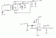
It's just a plain vanilla full wave bridge. If you want to get fancy, you can substitute chokes for the resistors in the filters, but for a unity-gain high-level stage, it's overkill.
SY, when using large negative voltages to tie the cathode resistor to, you will blow the grid if the positive voltage fails for some reason with the circuit shown.
A diode will take care of that, if it's a worry (one connection would be the cathode of the diode connected to the cathode of the tube, the anode of the diode to ground- it will limit the swing to 7 or 8 volts, but that's much more than required in this application). For me, it would be a worry if I'm using rare NOS tubes, but otherwise no; preamp tubes are pretty cheap compared to major power supply components.
I've built and used quite a few preamps using variations of this circuit (usually servoed instead of the output capacitor) and haven't lost a tube yet.
- Status
- Not open for further replies.
- Home
- Amplifiers
- Tubes / Valves
- Biasing a cathode follower?