Anyone know the Bias voltage to Monolith panels? I know the smaller Aerius use around 1800vdc, I have a pair of questionable mono panels and am wondering if I can power them off the Aerius Supply to test them.
This thread says it's 3200 V on the Monolith III.
https://www.martinloganowners.com/threads/monolith-iii-whats-the-voltage-to-the-diaphragm.15334/
Implied here as well.
https://www.diyaudio.com/community/threads/martin-logan-monolith-iii-transformer-specs.249587/
This one says 3500 V for an old Monolith.
https://www.martinloganowners.com/threads/monolith-prototype-system-pix.4675/
As a basic test to see if the panels work at all, you can run them on the Aerius interface. If you have a typical diaphragm coating failure, you can probably determine that with this setup. If you suspect an insulation failure of some kind, the lower voltages may not be enough to demonstrate that.
The bias decrease will cause an output difference of about -5 dB from what's intended for the Monolith panel. If the audio step-up transformer ratios are different, that will cause another change in output.
Differences in panel capacitance may cause some frequency response anomalies also.
Excellent, thanks very much Matt. Exactly what I needed to know. I suspect these are new in box but about 15yrs old. But as they haven't see light, they've been boxed all these years, I'm thinking they should be ok.This thread says it's 3200 V on the Monolith III.
https://www.martinloganowners.com/threads/monolith-iii-whats-the-voltage-to-the-diaphragm.15334/
Implied here as well.
https://www.diyaudio.com/community/threads/martin-logan-monolith-iii-transformer-specs.249587/
This one says 3500 V for an old Monolith.
https://www.martinloganowners.com/threads/monolith-prototype-system-pix.4675/
As a basic test to see if the panels work at all, you can run them on the Aerius interface. If you have a typical diaphragm coating failure, you can probably determine that with this setup. If you suspect an insulation failure of some kind, the lower voltages may not be enough to demonstrate that.
The bias decrease will cause an output difference of about -5 dB from what's intended for the Monolith panel. If the audio step-up transformer ratios are different, that will cause another change in output.
Differences in panel capacitance may cause some frequency response anomalies also.
I swear, it's amazing how many searches you can do and not come up with these links, I'm a member on MLO too but I guess I just didn't come up with the right search terms. Your help is much appreciated.
Glad I could help. Let us know how the tests go.
For some things, using an outside search engine can produce better results than the ones built into the forums. I don't really understand it, but I've had to resort to google searching at times even when hunting for one of my own posts.
For some things, using an outside search engine can produce better results than the ones built into the forums. I don't really understand it, but I've had to resort to google searching at times even when hunting for one of my own posts.
Long ago there was a procedure of raising Dayton-Wright voltage until bits of arcing start. And can be changed as needed. Never much serious arcing, just spitting sounds, because of vast resistance in series with the bias. But is that a worthwhile practice for this ESL or others?
For a speaker with a known operating bias, I would use that value. I generally assume the manufacturer knows their panel/insulation better than I do. You might get away with higher than specified bias if you live in a low humidity area, have clean air, tight temperature control, and a panel that's inherently very stable, but if you are operating on the ragged edge little things can push you over more easily.
When working on your own designs, dialing the bias up to the crackle or collapse point and then backing off is a pretty typical thing to do. Diaphragm tension/span, insulation specs., etc. all influence the panel's stability/voltage limits.
Even with a stable panel, operating at very high bias voltages may not be advisable. You may increase leakage/corona, which could degrade the diaphragm coating or stator insulation over time. You may be sacrificing ultimate output as well, since there is an optimum bias/audio voltage ratio. Exceeding that from a bias standpoint may increase the voltage sensitivity, but it will negatively impact maximum output.
The Dayton-Wright approach of using insulating gas was unique, so I'm not familiar with their exact limits. I've never thought about that approach seriously, so never ran any numbers on it. The discussion above is for more typical panels operating in air.
I think 8-10,000kV with gas and I run his cells in air at around 6kV, give or take a kV or two. DW argued for HV to have louder output for movie theatres (pairs stacked, but what an optimist!) but opinions differ on the exponent of the increase.The Dayton-Wright approach of using insulating gas was unique, so I'm not familiar with their exact limits. I've never thought about that approach seriously, so never ran any numbers on it. The discussion above is for more typical panels operating in air.
Some of the coating in my cells may have migrated to cell-heaven (I hope) and Bolserst who examined a sample thinks so. But that's not bad for cells maybe 50 years old (although in storage many years in-between).
B.
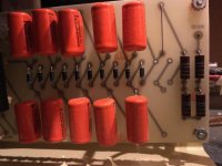
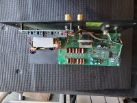
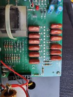
I'm not sure where/when I got them, but attached are some pics of the Monolith I, and Monolith III power supply boards.
Inspection suggests both are putting out roughly 3.2kV
The Monolith I has a 10 stage HV multiplier fed by 230Vrms. (230*sqrt(2)*10 = 3.25kV)
...a bit sketchy with 650VDC on caps rated for 600VDC
The Monolith III uses a newer HV circuit with 12 stage multiplier and Zener string limiter set to 271V. (271*12 = 3.25kV)
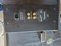
The Aerius came with 2 different versions of HV power supply depending on age. Both I believe produced 2.4kV.
Either can be modded to match the 3.2kV Monolith bias value if desired at some point in the future.
It will be safe to use the Aerius interfaces to test the Monolith panels.
As mattstat mentioned, the SPL will be down a few dB and the HF response will likely suffer a bit due to the larger capacitive load of the Monolith panels.
But, you will definitely know if the panels are operable or in need of new conductive coating on the diaphragm.
Inspection suggests both are putting out roughly 3.2kV
The Monolith I has a 10 stage HV multiplier fed by 230Vrms. (230*sqrt(2)*10 = 3.25kV)
...a bit sketchy with 650VDC on caps rated for 600VDC
The Monolith III uses a newer HV circuit with 12 stage multiplier and Zener string limiter set to 271V. (271*12 = 3.25kV)
The Aerius came with 2 different versions of HV power supply depending on age. Both I believe produced 2.4kV.
Either can be modded to match the 3.2kV Monolith bias value if desired at some point in the future.
It will be safe to use the Aerius interfaces to test the Monolith panels.
As mattstat mentioned, the SPL will be down a few dB and the HF response will likely suffer a bit due to the larger capacitive load of the Monolith panels.
But, you will definitely know if the panels are operable or in need of new conductive coating on the diaphragm.
Attachments


SPL increased +6dB per doubling of HV as long us you stay below the break-down voltage gradient for the gas the ESL is operating in....DW argued for HV to have louder output for movie theatres (pairs stacked, but what an optimist!) but opinions differ on the exponent of the increase.
https://www.diyaudio.com/community/...nance-change-with-hv-bias.147801/post-2378013
Thanks again for the sample panels. I still owe you some measurements and write-up for the DW panels...not much info at all available for them elsewhere.Some of the coating in my cells may have migrated to cell-heaven (I hope) and Bolserst who examined a sample thinks so.
Yes, the coating on one of the panels had pretty much all evaporated. Even after charging for 48hrs it didn't produce the expected output and NF measurements showed hot spots surrounded by areas of relative silence. Exhaling warm moist air on the coating side of the panel would perk up the panel to full output for 30seconds or so.
I'll check to see if eBay has one of those warm air exhaling machines. Kidding aside, thanks for your good help.... Exhaling warm moist air on the coating side of the panel would perk up the panel to full output for 30seconds or so.
B.
- Home
- Loudspeakers
- Planars & Exotics
- Bias voltage to ML Monolith panels.