I'm planning to convert my 45 output valve from cathode bias to fixed bias. I put together a little spreadsheet to help with calculating the values required so I'm posting it in case it helps anyone.
Basically is assumes the trimmer has resistors above (top) and below (bottom). Tell it the voltage range (top and bottom), the target range you want to be able to trim between and the desired mA flowing through the stack and it will give a guide to the values.
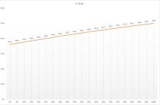
Once that's done give it the ACTUAL trimmer and resistor values you have available and it will calculate the voltage out from the trimmer in 5% steps from 0% to 100% - obviously the total resistance of the stack changes and therefore the current flow also changes, the attached graph shows for example a pot which I initially expected to give me control between 30v and 50v, actually I get 36v to 50v.
Turns out I can't attach a spreadsheet. PM if you need it. Of course if I've cocked up my calcs please let me know :-(
Basically is assumes the trimmer has resistors above (top) and below (bottom). Tell it the voltage range (top and bottom), the target range you want to be able to trim between and the desired mA flowing through the stack and it will give a guide to the values.
Once that's done give it the ACTUAL trimmer and resistor values you have available and it will calculate the voltage out from the trimmer in 5% steps from 0% to 100% - obviously the total resistance of the stack changes and therefore the current flow also changes, the attached graph shows for example a pot which I initially expected to give me control between 30v and 50v, actually I get 36v to 50v.
Turns out I can't attach a spreadsheet. PM if you need it. Of course if I've cocked up my calcs please let me know :-(
Attachments
OK I've stuck the spreadsheet on my Google Drive and it can be accessed here
https://docs.google.com/spreadsheets/d/13fu7wYEgERIjrvx7blSX93xHl2XeFPIK8a4jt4jOHf4/edit?usp=sharing
All comments and improvement welcomed ...
https://docs.google.com/spreadsheets/d/13fu7wYEgERIjrvx7blSX93xHl2XeFPIK8a4jt4jOHf4/edit?usp=sharing
All comments and improvement welcomed ...
Please ignore this ... I realise that my basic assumption is incorrect ... "obviously the total resistance of the stack changes"
Thanks - I did a similar thing which can be accessed here
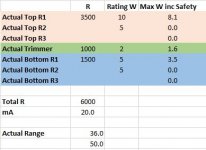
I was quite concerned about exceeding the power rating of the potentiometer used in the voltage divider, especially as the power rating is only relevant if applied along the entire track. Adjust the wiper to half way and the power rating is halved (assuming linear pot) and at the same time you're probably increasing the current through it.
Looking for reliability and longevity, I decided some sort of calculation was necessary to ensure that at no point in the adjustment range is the effective power rating of the pot exceeded.
So you can download it from the post linked above if it's helpful.
(screenshot if it below - cells have roll-over comment boxes explaining usage)
- Status
- Not open for further replies.