I have two questions. First is bias tap. How would this transformer be wired for a 70v bias tap and 400 volt center tap? I am using one transformer for 2 X 300b and the other for 2 X 6sn7. How do I handle the grounding? I included the secont transformer
Attachments
Last edited:
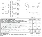
That looks like 800 & 140 VCT on that secondary to me. I think the 70 & 400V labels are transposed, Y/Y = CT.
No, I doubt that - Antek likes to mark their lead and trail wires similarly colored on each winding, so I'd use Yellow - White/Yellow - White
Last edited:
No, I doubt that - Antek likes to mark their lead and trail wires similarly colored on each winding, so I'd use Yellow - White/Yellow - White
So 400 & 70 with no CT?
Oh, sorry OP...
And I realized I made a mistake in my previous post.
Assuming the schematic is correct, you won't get 400CT from that transformer. You can get 800CT or 400 non CT. 800CT would be Yellow -Yellow/Grey - Yellow.
Bias would be taken from one of the 70v windings. Your schematic doesn't show any need for a bias voltage, are you using it for a different circuit?
You could get 400CT by feeding 120 into the primary if it’s wired for 240. Only half the VA capacity, but it works. The bias tap would only be at 35 volts, but you can always voltage double it, because presumably you won’t need much current. The bias rectifier needs to be capacitively coupled regardless of how you hook it up.
I am using the 400-0-400 transformer to power the two 300b's. I want to use a separate transformer to power the 6sn7's. I want to use fixed bias for the 300b. This allows the use of a single 5u4g for the 300b's and SS rectification for the 6sn7's. How would I ground the two circuits? Perhaps it is not possible to do it this way.
Last edited:
I would be inclined to use a 400-0-400 to power the whole works, and drop the B+ for the preamp with a mosfet regulator if needed. Or just RC filtering. It would be possible to use a separate transformer to power the SN7’s, but on something this simple, why? You might do it if you were using direct coupled drive to the output tube, and needed the whole front end to come up and stabilize before throwing the switch to the final stage B+. A SET running in A1 isn’t going to need that. If you had something like a MC phono pre, you might want a separate supply to keep noise and crosstalk down. But nothing like this is going on here.
The schematic you show uses cathode bias, where a separate voltage isn’t needed. I suppose you intend to dispose of the cathode resistor and feed in a negative Vg1?
The schematic you show uses cathode bias, where a separate voltage isn’t needed. I suppose you intend to dispose of the cathode resistor and feed in a negative Vg1?
- Status
- This old topic is closed. If you want to reopen this topic, contact a moderator using the "Report Post" button.
- Home
- Amplifiers
- Tubes / Valves
- Bias tap