I am working on a pair of MKII amps, and just got one powered up, but I have red plating on the rear tube. I rotated the tubes and the red plate is on the same socket each time. I looked over the circuit and everything seems to be wired fine. The only major change I installed away from the original circuit and that I added a second bias pot and duplicated the Dynaco schematic. Is there any reason that this would be causing extreme shift to the rear tube? It is hogging and the front tube is essentially off. Could something with the driver cause this?
I really hate to think I put all this work into a bad output transformer. It ohms out fine, but I have seen them arc once voltage is applied.
Thanks!
I really hate to think I put all this work into a bad output transformer. It ohms out fine, but I have seen them arc once voltage is applied.
Thanks!
Attachments
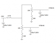
No, what happened is this: the bias string forms a voltage divider with the 4k7. By repeating the bias string, you cut the voltage across the bias string by half. The fact that it's at the same socket is a bit troubling, so you want to check the connections there very carefully, especially the orientation of the pot. Also you might want to swap out the coupling cap just to be safe.
The final filter cap that you have is likely to cause a significant lag in the adjustment. I'd move it to the other side of the bias string.
The final filter cap that you have is likely to cause a significant lag in the adjustment. I'd move it to the other side of the bias string.
What is the voltage on the KT88 grids ? This can be measured with theI am working on a pair of MKII amps, and just got one powered up, but I have red plating on the rear tube. I rotated the tubes and the red plate is on the same socket each time. I looked over the circuit and everything seems to be wired fine. The only major change I installed away from the original circuit and that I added a second bias pot and duplicated the Dynaco schematic. Is there any reason that this would be causing extreme shift to the rear tube? It is hogging and the front tube is essentially off. Could something with the driver cause this?
I really hate to think I put all this work into a bad output transformer. It ohms out fine, but I have seen them arc once voltage is applied.
Thanks!
KT88 removed and the probe in pin5 of the kt88 sockets. Also check that
both pots actually varies the voltage on pin5
If when both seems to work , adjust the pot for max bias ( most negative ) and reseat the tubes. Then adjust the bias to 50mA per tube.
I am working on a pair of MKII amps, and just got one powered up, but I have red plating on the rear tube. I rotated the tubes and the red plate is on the same socket each time. I looked over the circuit and everything seems to be wired fine. The only major change I installed away from the original circuit and that I added a second bias pot and duplicated the Dynaco schematic. Is there any reason that this would be causing extreme shift to the rear tube? It is hogging and the front tube is essentially off. Could something with the driver cause this?
Another thing that's not right here is the absence of guard resistors. (See attached) Pots have a nasty habit of sometimes disconnecting. With this particular bias arrangement, that means no bias for the final, and red plating or even poofage of finals and possibly OPTs as well. See how R18-19 are connected. These are both 10M resistors: too large to have any real effect on the bias level or the rate of change of the bias pots. However, should a slider lift off the track, it will provide full cutoff bias to that final.
The other problem with the included schemo is those 100uF capacitors on the control grid side. That's way too much and will lead to an excessive delay in bias level changes. The whole problem could be due to that alone: turning the bias pot too far because it takes so long for that 100uF capacitor to change/discharge to the new voltage.
I really hate to think I put all this work into a bad output transformer. It ohms out fine, but I have seen them arc once voltage is applied.
Thanks!
That needs to be checked out, and it's not a good sign.
Attachments
Hi Miles,
I fond a cold joint on pin 1 on one of the tubes. That fixed the no boas issue. I then added another diode and cap to make two separate bias circuits. That seems much more stable.
What value resistor should I install there between the wiper and the input as a safety?
Thanks!
I fond a cold joint on pin 1 on one of the tubes. That fixed the no boas issue. I then added another diode and cap to make two separate bias circuits. That seems much more stable.
What value resistor should I install there between the wiper and the input as a safety?
Thanks!
I actually know the answer to this unfortunately. It lets bias go to maximum bias and redplates your output tubes to death. Especially, if say, if you are three rooms away cooking dinner
Well think about it..
That doesn't have to be the case!
The bias supply is dropped via the resistors as a divider..
What happens if you put a resistor to the bias supply and put the tube to the resistor then put a pot from the resistor to Gnd?
If the pot goes open you get bias supply to tube..(full no drop)..shuts the tube down.
You could try a 39K with 100K pot or 39K with a 50K pot and a 22K to Gnd to keep some resistance in the grid when adjusting.
What you need to do is measure the bias voltage you need to get reasonable adjustment and set it up to suit with a multi meter then try it on a tube.
You could try 39K as the resistor and fit 100K pot or 39K with a 50K pot and a 22K to ground to keep some resistance in the grid circuit.
You need one resistor and pot per tube..with a resistor after the pot if you want to prevent grid current should the pot be adjusted to the ground side by accident.
You have to play with the values but it works..the current required for bias is small so the resistor can be a large value.
I will leave you with that idea to think about..have fun
Regards
M. Gregg
Last edited:
I was just about to say that, but I got beat!What happens if you put a resistor to the bias supply and put the tube to the resistor then put a pot from the resistor to Gnd?
If the pot goes open you get bias supply to tube..(full no drop)..shuts the tube down.
Excellent idea to adopt.
Wipers on pots do go open circuit sometimes, be it age, corrosion whatever.
I have paid for my mistake, that's how I learnt - you got it free here.
The only thing you have to watch,
is that the parallel path of the resistors to the pots don't exceed the bias supply current if all the pots are shorted to ground.
ie if all the pots were set to minimum resistance the value of the 39K's in parallel must not allow bias current to exceed the bias supply winding current.
Regards
M. Gregg
- Status
- This old topic is closed. If you want to reopen this topic, contact a moderator using the "Report Post" button.
- Home
- Amplifiers
- Tubes / Valves
- Bias Schematic