The first image looks like low frequency noise/hash but the second seems to show HF oscillation. If the relay is not clicking then you need to repeat the measurements but this time measure before the relay (so measure at the amp output directly (on the 0.22 ohm resistors). If the relay isn't clicking then the HF would couple across the relay via capacitive coupling and you might find the amplitude is much much larger at the amp itself.
the hsinks should get really hot normally, too hot for long term reliability - another ticking time bomb
Not on Class AB setting. The figures show the dissipation will be low, typically like most other commercial amps running low bias.the hsinks should get really hot normally
Not on Class AB setting. The figures show the dissipation will be low, typically like most other commercial amps running low bias.
When the short between TP1 and TP3 is in place, at 36mv the right channel is warm like a class A/B amp. The left channel is now ice cold and I can't get it anywhere near 36mv (more like 1.5mv).
Last edited:
I'll have a look later. I'm on a different PC and the manual I just downloaded looks totally different to the one I was using the other day. Very odd.
Going back to post #1
Did the amp work OK before the recap? or had it got these issues before?
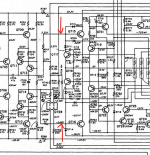
Its not a desperately easy circuit to untangle but I think you need to begin by looking at the voltage between the driver bases and comparing the two channels for a start.

Also look at the drive to the opto and compare between the two channels to make sure each is receiving the same drive signals.
Did the amp work OK before the recap? or had it got these issues before?
Its not a desperately easy circuit to untangle but I think you need to begin by looking at the voltage between the driver bases and comparing the two channels for a start.

Also look at the drive to the opto and compare between the two channels to make sure each is receiving the same drive signals.
I'll have a look later. I'm on a different PC and the manual I just downloaded looks totally different to the one I was using the other day. Very odd.
Apparently there are two versions of the technical manual. Are the instructions on how to adjust bias and quarter A clearer in one? Also, I saw online there's a version of the PM94 with an optional rectifier board (800) and the biasing is lower in class A. https://audiokarma.org/forums/index.php?threads/marantz-pm-94-project.937600/
I can't look back because I'm on a clean Windows install with. I've pulled the manual from HiFi Engine.Are the instructions on how to adjust bias and quarter A clearer in one?
Remember that however convoluted the bias control sees to be, ultimately the current is set by bringing those drivers into conduction and that is determined by the voltage difference between their bases.
I asked this because its important to know if we are chasing a real problem or something that has happened following the recap.Did the amp work OK before the recap? or had it got these issues before?
The channel that is cold needs the voltage to the drivers measuring to see what is going on there. Does that bias voltage (between the driver bases) alter as the presets are altered?
The amp worked fine after recap. However, the temperature of the left channel has always been higher than the right. When I checked the bias of the left channel, I noticed that it was off. After adjusting it, all of a sudden the bias started to show erratic behaviour (went high, then low etc.) That was the reason I replaced the trim pots.
You are going to have to do some detailed measurements to try and get a handle on what is happening. You need to look the points I have mentioned and you must determine if the bias is altering because of a problem or whether it is altering in response to the drive to the opto.
There are fusible resistors, but could they be the cause?Did you see if there are any fusible resistors? If there are, you need to replace them ...
- Home
- Amplifiers
- Solid State
- Bias problem Marantz PM-94