This is possible, I will check further tomorrow.The wiring is correct in the schematic. But perhaps a miswiring
I am really not sure why this would change anything and its a huge hassle to change but I will do so if I can't come up with anything else.Try cathode resistor bias.
The strangest thing to me is that when shorting the feedback to one chanel, the other one also becomes stabile again. But also that there is no audio coming through with any scenario.
This is so. While the amplifier os sustaining oscillations, there will not be any audio at its output. Normally oscillation (desired when building an oscillator for a transmitter por example; or not, when an amp is oscillating as is your case), the only limit for them are: grid being positive, drawing current and so, damping its source of signal; plate current cutoff because too negative grid signal or, finally, the voltages and currents available in the supply of the stage under consideration. Also try disabling one of the channels taking away the tubes from its sockets.
In any case, if the amplifier is maintaining oscillations, there is no room enough to amplify audio nor no other signal.
Many many decades ago, such a principle was used in superegenerative receivers for VHF and UHF mainly by ham radio builders like me. In those devices, a triode was wired as plain RF amplifier with a strong positive feedback, assisted returning the grid biasing resistor to a positive supply. Thus strong oscillations carry the tube violently from saturation to cutoff thanks an RC time constant; was maintained at a superadible frequency, say 40 or 50KHz. As the tube goes and backs from oscillation, the signal was detected thanks to grid leak as there was no room to amplify the RF signal itself.
There is coupling between channels through the common power supply.The strangest thing to me is that when shorting the feedback to one chanel, the other one also becomes stabile again.


Interesting for sure but I think I'd like to make it work like it is now first. There would be quiet a bit of work involved in making those modifications and if it sounds fine as it is I think I am moving on to making a new amp with all the lessons learned from this one. My fun is all in the design and build really 🙂Some mod's to think about 😉
Mona
Oh yeah that's true, my suspicion is that it's propagating through the 12AX7 bias resistor as that's shared between the channels at the moment(I will definitely change this as soon as I get to poking around the amp again) , but it's strange that doing the same thing to the different audio channel has so different results. I will have to check my wiring, that's pretty much the only thing I have left before I start ripping out componentsThere is coupling between channels through the common power supply.
If the circuit can be stable with the current power supply, then it's likely that the connections between
the first and second stages are swapped, making the overall feedback the wrong polarity.
the first and second stages are swapped, making the overall feedback the wrong polarity.
So, update on the whole issue:
Went through the wiring and found that the output was disconnected so there was no load, leading to this oscillation and no output. When I had fixed the wiring and got a pair of headphones in there it went away.
I put on some music and music came out, but the issue is not gone, bass frequencies and/or high volume(with high I mean normal listening volume) it starts blinking the LEDs and horrible pops come through the headphones.
Especially looked at the wiring for the NFB and was not able to find an issue with either chanel. Not saying there isn't one, but I didn't find one. The feedback is hooked to the right tube and to the correct section of the tube as well.
The instability now occurs periodically at any frequency bellow 4kHz when fed 150Vrms input from the signal generator. I probed the NFB into the tubes for both channels, blue is left, purple right. They are in very distorted from the clean sinus input and don't have the expected phase shifts either.
(the probe for yellow was set to 1x instead of 10x, therefore the different voltage scaling. The relative size displayed is correct.)
4kHz:

1kHz(between bursts of instability):

1kHz unstable:


For the most part the NFB looks the same for both the left and right channels except for some moments during the instability.
An issue for later is that I am getting some hum(sounds about the same as the hum from my isolation transformer so likely coupled from mains somehow) from the left audio chanel but none from the right one.
Went through the wiring and found that the output was disconnected so there was no load, leading to this oscillation and no output. When I had fixed the wiring and got a pair of headphones in there it went away.
I put on some music and music came out, but the issue is not gone, bass frequencies and/or high volume(with high I mean normal listening volume) it starts blinking the LEDs and horrible pops come through the headphones.
Especially looked at the wiring for the NFB and was not able to find an issue with either chanel. Not saying there isn't one, but I didn't find one. The feedback is hooked to the right tube and to the correct section of the tube as well.
The instability now occurs periodically at any frequency bellow 4kHz when fed 150Vrms input from the signal generator. I probed the NFB into the tubes for both channels, blue is left, purple right. They are in very distorted from the clean sinus input and don't have the expected phase shifts either.
(the probe for yellow was set to 1x instead of 10x, therefore the different voltage scaling. The relative size displayed is correct.)
4kHz:
1kHz(between bursts of instability):
1kHz unstable:
For the most part the NFB looks the same for both the left and right channels except for some moments during the instability.
An issue for later is that I am getting some hum(sounds about the same as the hum from my isolation transformer so likely coupled from mains somehow) from the left audio chanel but none from the right one.
Wait what? The cathode bias resistor???Oh yeah that's true, my suspicion is that it's propagating through the 12AX7 bias resistor as that's shared between the channels
It's not shared anymore, I just did that to troubleshoot the CCS and they now have individual resistors. Interestingly changed nothing thoughWait what? The cathode bias resistor???
Alright, just so I am understanding this right, this would be to tie the grid of the top tube to a fix voltage with a resistor divider?Did you tried the bootstrapping?. IMHO it may be part of the problem. The upper tube isn't being driven properly. Then he can do what he wants.
I have checked the polarity of all the NFB wiring several times now, and even though I really believed something would be up with it, I can't find a single wrong connection anywhere in the amplifier.
I think the bootstrapping the top tube and making C12 bigger and R8 and R12 smaller is my next move. Maybe doing a resistor bias if that doesn't make it all good, but that involves a lot of surgery because of how I built everything.
I have not rebuilt my amp according to that schematic no.This is the "bootstrapping" circuit already said. Are you using it?
So could I just grab the 250V from above the anode resistor and feed that with a cap to bellow the LEDs? That would be fairly easy to add if so 🙂
So could I just grab the 250V from above the anode resistor and feed that with a cap to bellow the LEDs? That would be fairly easy to add if so 🙂
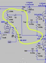
You are missing the point - part of the audio signal is transferred due to the tap between the two series plate resistors.
Bootstrapping is an AC process, not DC.
So do I need to rebuild the entire LTP or can I still do that from the top of the current load resistor? Rebuilding the LTP will take a few hours I don't have todayYou are missing the point - part of the audio signal is transferred due to the tap between the two series plate resistors.
Bootstrapping is an AC process, not DC.
That's how it works.So do I need to rebuild the entire LTP or can I still do that from the top of the current load resistor? Rebuilding the LTP will take a few hours I don't have today
Ma
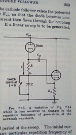
May be also a DC mechanic if in place of a cap you put a neon bulb, a VR or the like. It has been used in the generation of sawtooth generators too replacing the top resistor (this between boot cap and Ebb) with a diode.You are missing the point - part of the audio signal is transferred due to the tap between the two series plate resistors.
Bootstrapping is an AC process, not DC.
Attachments
Well I just put in the 1u caps from the 250V rail to the bottom of the LEDs of the top tubes and made the feedback cap 10x larger and now the poping is gone 😀 I do however now have a lot of volume in one chanel and not much in the other one and the chanel with the good volume also has significant humm(though the hum is not new, its something that's been there since I first got any sound out)
- Home
- Amplifiers
- Tubes / Valves
- Bias LED blinking and no sound out