Finally have everything hooked up in my 8136 OTL headphone amp(schematic attached and the thread can be found here), flipped on the power, PSU voltage is good, tubes glow nice, power draw is within 3mA of expected for the HV part, bias to the 8136s is a bit more than expected(~0.5V off) but then I looked into the amp and saw the LEDs blinking at ~5Hz.... and no sound comes out the headphones even with excessive signal in and the volume all the way up.
Found and fixed a couple of issues already like the CCS not working(replaced with a resistor now), the 56K bleed resistors not being hooked up and the LED bias not being connected properly(after fixing this I got the blinking I am now seeing).
My intuition is that the 47u cap parallell to the LEDs is the issue here but I have not tried cutting it out yet as that's a fair bit of work to put back if that's not it. Also not sure as to why that didn't show up in the simulation if so.
The other idea I have is that my crappy wiring has made enough inductance somewhere to create an LC oscillator but I don't really think that's what it is, it's not like I've wound all my wires into a coil, it's just far from actually good...
Could also be something up with the NFB but I am not sure what if that's the case.
Obviously something else could be disconnected but poking around I haven't noticed anything besides what I have already fixed and as its the same for both the left and right audio channels and all LEDs are blinking at the same rate I am more inclined to say that something is up with my circuit.
Here is a scope image with the AC(as it rests at about 3.7V) over the LEDs(yellow) and the output to the headphones(blue). The voltage out seems really really extreme at over 50V, but no sound out. The output frequency is the same as the cathode voltage but a different waveform. There is no change with signal applied, input open or input shorted:

A scope image of the plate of the 12AX7(node called Bot in the sschematic in blue and the bias in yellow. First with signal input and second without.


Schematic in LTSpice:

To me it looks like the issue is in the 8136 circuit and that the output from the 12AX7s get shorted to ground at roughly a frequency of 5Hz. The Bot node looks alright besides the dips, it seems to be resting a bit low but the signal seems to be getting through fine.
*edit:
The PSU schematic is now attached
Found and fixed a couple of issues already like the CCS not working(replaced with a resistor now), the 56K bleed resistors not being hooked up and the LED bias not being connected properly(after fixing this I got the blinking I am now seeing).
My intuition is that the 47u cap parallell to the LEDs is the issue here but I have not tried cutting it out yet as that's a fair bit of work to put back if that's not it. Also not sure as to why that didn't show up in the simulation if so.
The other idea I have is that my crappy wiring has made enough inductance somewhere to create an LC oscillator but I don't really think that's what it is, it's not like I've wound all my wires into a coil, it's just far from actually good...
Could also be something up with the NFB but I am not sure what if that's the case.
Obviously something else could be disconnected but poking around I haven't noticed anything besides what I have already fixed and as its the same for both the left and right audio channels and all LEDs are blinking at the same rate I am more inclined to say that something is up with my circuit.
Here is a scope image with the AC(as it rests at about 3.7V) over the LEDs(yellow) and the output to the headphones(blue). The voltage out seems really really extreme at over 50V, but no sound out. The output frequency is the same as the cathode voltage but a different waveform. There is no change with signal applied, input open or input shorted:
A scope image of the plate of the 12AX7(node called Bot in the sschematic in blue and the bias in yellow. First with signal input and second without.
Schematic in LTSpice:
To me it looks like the issue is in the 8136 circuit and that the output from the 12AX7s get shorted to ground at roughly a frequency of 5Hz. The Bot node looks alright besides the dips, it seems to be resting a bit low but the signal seems to be getting through fine.
*edit:
The PSU schematic is now attached
Attachments
Last edited:
Breakdown of an insulation, capacitor dielectric or heater-cathode for example?
Are the heaters elevated?
Are the heaters elevated?
I belive the heaters are floating, they are just straight out of the transformer with no point tying them to the rest of the circuit. I assume that's another issue to the list? 🙂Breakdown of an insulation, capacitor dielectric or heater-cathode for example?
Are the heaters elevated?
At least to me the 5Hz frequency seems strange if it's the heaters, but I don't belive it's the caps as they should be more than fine voltage wise and all tested perfectly before assembly
The actual power supply circuit is not posted or simulated.
Seems like a LF instability propagated through the power supply.
Use a lab supply instead to verify this.
Seems like a LF instability propagated through the power supply.
Use a lab supply instead to verify this.
Well I guess maybe its time to see if my HP 600V supply works then I suppose 🙂The actual power supply circuit is not posted or simulated.
Seems like a LF instability propagated through the power supply.
Use a lab supply instead to verify this.
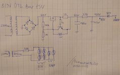
The PSU is a little fancy I guess but nothing I'd expect to cause anything like this and the voltage on the Fluke multimeter looks stabile to within a volt for both the 250V and 450V. On the voltages where I see this strange waveform it varies significantly so I'm not sure it's sneaking through the HV supply.
Either way, here is the schematic(on a piece of paper because I don't have a computer close atm):
Add a decoupling capacitor for the low voltage input stage as well. Perhaps an additional RC network for it is best.
If you use the HP supply, the oscillation may still not go away. The 200V Zener impedance could be responsible.
Do the two 12AX7 plates go "up and down" together at 5Hz?
If you use the HP supply, the oscillation may still not go away. The 200V Zener impedance could be responsible.
Do the two 12AX7 plates go "up and down" together at 5Hz?
Last edited:
This schematic has a big error of design. The bottom tube of the OTL has its cathode grounded, and its grid "sees" the normal signal input from phase splitter and amplifies it normally.
But top tube is acting as a cathode follower with the signal referenced also to ground and not to its cathode and the signal output will be severely distorted.
My suggestion is to take a read about OTL's and its design. I would refer you to some US patents available at Google Patents:
US 3123780; US 3092783; US 2931990; 2773136; UD 2774773 (the most interesting); US 2659775; US 2488567. All them were of great help in my design using 6JN6 pentodes.
Yes, even Mr. Futterman had problems like this. I don't believe he ever resolved them.
Later "keepers of the flame" did do so, however.
Later "keepers of the flame" did do so, however.

You need a diode before the 1780u capacitor or the MOSFET will not drop voltage correctly (because of back-feed through the MOSFET body diode).The PSU is a little fancy I guess but nothing I'd expect to cause anything like this and the voltage on the Fluke multimeter looks stabile to within a volt for both the 250V and 450V. On the voltages where I see this strange waveform it varies significantly so I'm not sure it's sneaking through the HV supply.
Maybe you wired your NFB out of phase by accident? ("Bot and Top" back to front?)
It's there, I just forgot to draw it 🙂You need a diode before the 1780u capacitor or the MOSFET will not drop voltage correctly (because of back-feed through the MOSFET body diode).
Maybe you wired your NFB out of phase by accident? ("Bot and Top" back to front?)
I will check that the NFB is hooked up to the right section.
I don't believe this is the case? The signal goes through a decoupling cap and then a resistor network connects it to the grid and its cathode, giving the signal an appropriate DC level.But top tube is acting as a cathode follower with the signal referenced also to ground and not to its cathode
I will add a decoupling cap after the 200V Zener and see if that helps, probably something like 3uF as that's what I've got around. I have not checked if they go up and down together, but the LEDs for the bottom and top tube of each channel blink in unison. The right and left sides seems to be in counterphase(at least in the short video I took for reference).Add a decoupling capacitor for the low voltage input stage as well. Perhaps an additional RC network for it is best.
If you use the HP supply, the oscillation may still not go away. The 200V Zener impedance could be responsible.
Do the two 12AX7 plates go "up and down" together at 5Hz?
But the cathode does float over the load voltage and the bottom tube signal. If you don't understand it and continue trying the circuit as it is now, you will continue having problems and scratching your head.I don't believe this is the case? The signal goes through a decoupling cap and then a resistor network connects it to the grid and its cathode, giving the signal an appropriate DC level.
My suggestion is to take a break and read from the references I cited and/or any other. And learn. And think.
He means the top triode needs more drive voltage than the bottom triode, for perfect balance. However, this would not stop the circuit from functioning as it is, so you can save any 'perfection' mods for later.I don't believe this is the case? The signal goes through a decoupling cap and then a resistor network connects it to the grid and its cathode, giving the signal an appropriate DC level.
I would make C12 bigger and make the feedback resistors (R8 & R12) much smaller, to try to reduce any phase shift in the feedback path. Do you still get oscillation if you short out R8? (i.e. removing the feedback)
Last edited:
Having read through all these patents and pondered at my circuit I am still unsure as to what you are getting at. One of them even has a drawing just like my stage except that the LEDs are resistors and instead of beam tetrodes they have triodes.But the cathode does float over the load voltage and the bottom tube signal. If you don't understand it and continue trying the circuit as it is now, you will continue having problems and scratching your head.
My suggestion is to take a break and read from the references I cited and/or any other. And learn. And think.
Is the issue that the signal from the LTP has some sort of tie to ground or that it dosnt have a tie to ground?
Alright, is this because of the LTP not giving perfectly symmetrical signals or is this a phenomena of the SEPP topology?He means the top triode needs more drive voltage than the bottom triode, for perfect balance. However, this would not stop the circuit from functioning as it is, so you can save any 'perfection' mods for later.
I would make C12 bigger and make the feedback resistors (R8 & R12) much smaller, to try to reduce any phase shift in the feedback path. Do you still get oscillation if you short out R8? (i.e. removing the feedback)
I am definitely not looking for perfection from my first bigger project of my own design, I'm just looking to learn and gain experience 🙂 I've learnt a huge amount already so I'm looking forward to applying that to my next amp 😀
I'll add shorting R8 to the list of things to try!
So far the list is:
Check that the NFB is hooked up to the right tube sections
Short R8 to see if the NFB is causing the issue
Add a decoupling cap after the 200V Zener
Change the NFB resistors and capacitors
I'll write back later when I get some time in the lab
The use of triodes or pentodes from the point of view of the signal handling is irrelevant. It also happens with JFETs, MOSFETs & BJT providing you are using only one polarity of such, P or N and not mixing them. Only changes impedances and amounts of amplification. What you need is to bootstrap the anode of the phase splitter who is wired to the top tube (be it of any kind) in order to have the proper voltage at its grid.
Try for a moment to get rid from leds and use classic cathode resistors and capacitor for biasing method.
Try for a moment to get rid from leds and use classic cathode resistors and capacitor for biasing method.
It's the SEPP. The top triode is a cathode follower (gain <1), lower triode is a gain stage (gain usually >1). They only acheive identical gain if the load is a short circuit. But don't worry about that now.Alright, is this because of the LTP not giving perfectly symmetrical signals or is this a phenomena of the SEPP topology?
So, results:
The NFB is connected according to the circuit
Decoupling cap after zener did nothing
Shorting R8 on one of the 12AX7s stopped the oscillation and makes the amp draw 3mA less current from the PSU.
Shorting R8 on the other side doesn't take away the oscillation and the amp draws an additional 2mA.
edit
And no sound in any of the cases
Any ideas?
Shorting R8 removes the overall loop feedback, so the feedback polarity may be wrong on that channel.
Try swapping the connections between the 12AX7 plates and the output stage grids, to reverse the feedback polarity.
Try swapping the connections between the 12AX7 plates and the output stage grids, to reverse the feedback polarity.
- Home
- Amplifiers
- Tubes / Valves
- Bias LED blinking and no sound out