A failed opto sounds reasonable. A good but not conclusive test is to measure the volt drop across the LED part of the opto when it is supposed to be on. A good LED will drop around 2 volts give or take. If its open circuit then you will see a much higher voltage across it.
You can turn the bias as low as you want too and in all probability it won't make any audible difference. 30 mv is only around 60 milliamps current though (still small) so I would just set it up as per the recommendations.
The higher the bias, the more output can be delivered in Class A but at just 60 ma current its all academic anyway. 60ma or zero milliamps, it won't affect the actual power output at all. For an amplifier of this sort to run in Class A would need a bias current of around 10 amps 😀
Thanks for all info , compared both channels one working at increased 100ma bias and one on 5mV without dynamic switch.
I didnot hear no difference on low freq like 100hz maybe very little audible on 10 000hz or up.
Yesterday i turned working channels dynamic adjust down to minimal 10mV.
I didnot hear no difference on low freq like 100hz maybe very little audible on 10 000hz or up.
Yesterday i turned working channels dynamic adjust down to minimal 10mV.
You are welcome 🙂
I would just fix the amp with a new opto and adjust it correctly because those settings will be optimal for the design. The energy saved is minimal, just a matter of a few watts.
I would just fix the amp with a new opto and adjust it correctly because those settings will be optimal for the design. The energy saved is minimal, just a matter of a few watts.
I think il do it, il need new potensiometers aswell and maybe upgrade to closed type more accurate ones.
This is best material i have found about denon optical class a
Google'i tõlge
It seems extremely small distortion difference.
Google'i tõlge
It seems extremely small distortion difference.
Vanishingly small I would say.
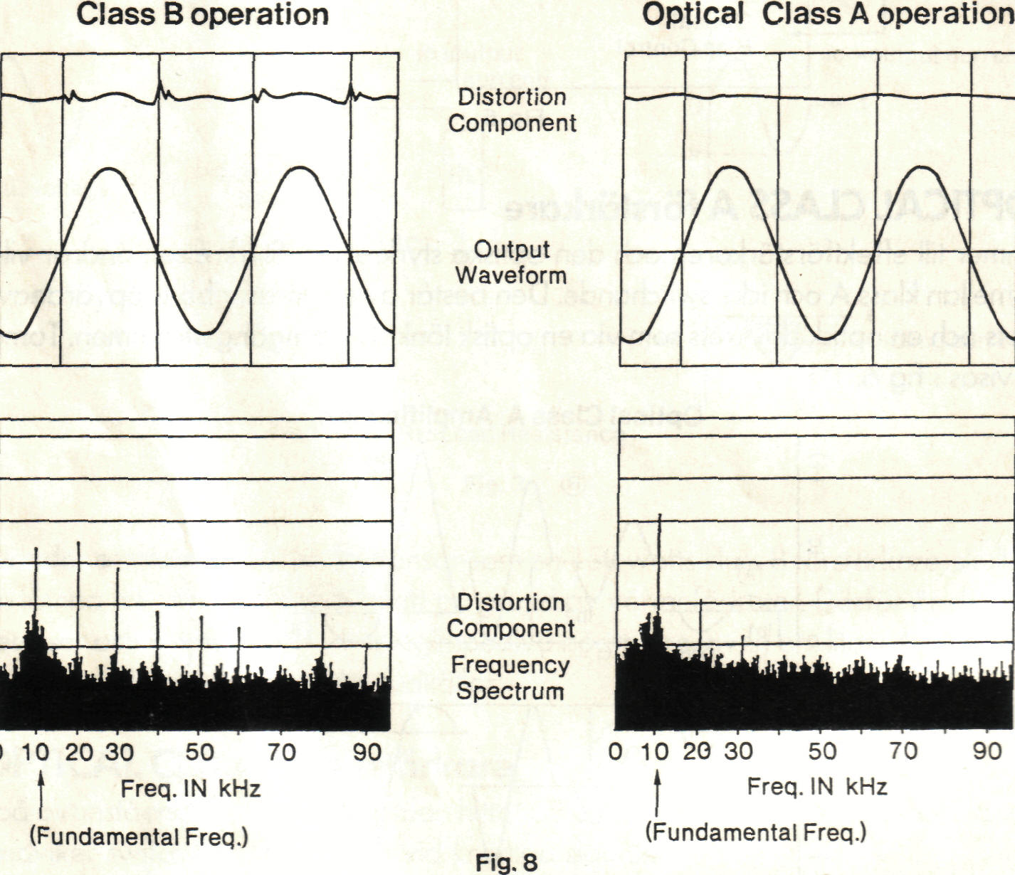
I dont know test conditions but if i drag one part of image on another i see that it increases distortion peak at around 10 000khz and reduces overall. Does class B mean no bias voltage?
Last edited:
Without knowing the vertical scale its a bit meaningless really, but class B can easily achieve 0.005% at 10Khz.
Yes, the definitions get blurred.
Class B means each device conducts for half the cycle with no overlap. No mainstream audio amps are true class B and those that describe themselves as such are really class ab where a little bias current flows all the time (like yours).
Class A means the output devices NEVER cut off and current flows all the time. Class A falls into different groups such as single ended and push pull but the same applies. Either of the ouput devices must never reach cut off. So that means any class A amp has huge quiescent current flowing all the time. Amps (like yours) are not class A by any accepted definition. Same goes for all the "sliding bias" class a schemes. The correct definition has been around years and is the one engineers use.
Thanks again for all explaining.
If i understand right if bias for both channels would fail completely amp turns class b and distortion like on left image will increase and on right is distortion of a/b class amp.
If i understand right if bias for both channels would fail completely amp turns class b and distortion like on left image will increase and on right is distortion of a/b class amp.
Last edited:
The distorsion graph above, the one on the left has something more than the right graph: It is not distorsion per se, as it does not varies with the input signal. It would be added to any non-dc signal. What is added are harmonics of the 10khz signal. And human ears find those harmonics harsh.
I am just done adjusting my PMA-909r, I was surprised to not find a dc offset adjustment, but it didn't need any.
What I was surprised, is that the 2nd set of adjustment potentiometers behavior. The service manual indicates to adjust them for a reading of 30mv at the test points. Turn it too low, you get < 5mv, too high you get < 5mv. There IS a sweet spot in between that gives you 30mv, be patient you will find it.
My local electronic store had a sale on toroidal transformers. Yes, the 980r can use one.
- Home
- Amplifiers
- Solid State
- bias/idle current adjusting