I am building a 6-channel amp with LM3886's, and due to layout reasons uses just a 0.1uF poly cap on the boards for the mute bypass. I figured I would come up with something later.
Then I realized that these nodes should not be driven with voltage, but rather current. Therefore, off loading this from the amp PCB did not save on component count.
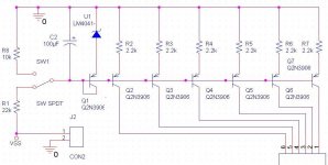
Then I thought: How can I do this better. I came up with the below circuit.
A single resistor (R1, 22k) sets the turn on delay into a single capacitor (C2, 100uF). This is used to bias a current mirror string. As there is plenty of overhead voltage, I can drop 1.2V across a shunt bandgap, (U1, LM4041-1.2). Similarly, a 5V regulator can be used in place of the shunt reference, or just about any zener value below 10V.
This approach definitely has a higher component count, but allows the changing of single components to change the characteristics of all amplifiers. Another advantage is that is provides constant bias regardless of supply voltage. This would be usefull if someone wanted to operate at 40V for 4ohm loads, and 80V for 8 ohm loads.
Then I realized that these nodes should not be driven with voltage, but rather current. Therefore, off loading this from the amp PCB did not save on component count.
Then I thought: How can I do this better. I came up with the below circuit.
A single resistor (R1, 22k) sets the turn on delay into a single capacitor (C2, 100uF). This is used to bias a current mirror string. As there is plenty of overhead voltage, I can drop 1.2V across a shunt bandgap, (U1, LM4041-1.2). Similarly, a 5V regulator can be used in place of the shunt reference, or just about any zener value below 10V.
This approach definitely has a higher component count, but allows the changing of single components to change the characteristics of all amplifiers. Another advantage is that is provides constant bias regardless of supply voltage. This would be usefull if someone wanted to operate at 40V for 4ohm loads, and 80V for 8 ohm loads.
Attachments
The mute current must flow from the IC to the negative rail, not from ground to the IC. The datasheet contains an equivalent schematic. That might be helpful for the circuit design.
- Status
- Not open for further replies.