I do like the 300B, but I don't like the hum. The last time it was worked on Dennis Boyle did a few things to it including putting in one of those variable wire wound resistors for adjusting the Bias. I don't like trying to adjust those things when the amp is on. The chassis is heavy chromed steel and is to heavy to hold up while you stick your hand around a hot 300B. So I decided to put a pot in. I got 2 100 ohm, 10 turn precision pots, drilled the holes and will wire it in where the resister is. Fine.
I haven't done this before and figure the 1st and last terminals on the pot, but there is one thing I am curious about. There is a 10 uF Poly paralleled with the 100 ohm resistor. What do I do with that? It must help with the hummm somehow or Boyle wouldn't have put it in there I don't think.
I haven't done this before and figure the 1st and last terminals on the pot, but there is one thing I am curious about. There is a 10 uF Poly paralleled with the 100 ohm resistor. What do I do with that? It must help with the hummm somehow or Boyle wouldn't have put it in there I don't think.
I suggest you look into Rod Coleman and Guido Tent and their filament solutions.
It's not simply a matter of hum. Proper filament supply provides significant (not subtle at all) sonic benefits.
It's not simply a matter of hum. Proper filament supply provides significant (not subtle at all) sonic benefits.
Hum can come from many other sources too... but if you are certain that its only coming from the filament, here is a nice example of how an AC filament circuit might look:
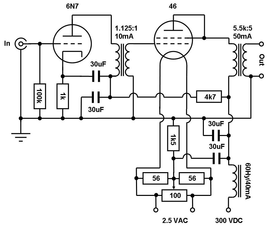
Take a close look - only ONE 100 Ohm pot is used. The middle pin goes to the cathode resistor. Its pretty easy. With the 300b the filament voltage is 5V, so it will still probably a very little bit. But if you have LOTS of hum then it is not only coming from AC heaters.
Tip: Make sure all AC wiring is tightly twisted. Check to make sure you have no ground loops (use a decent star or bus ground method).
As MrCurwen notes, you can build DC filament supply with solid state regulation. You can also do an old-school DC filament supply using chokes.
Best regards
Ian
Last edited:
The hum is not bad, it is just there. This amp is quite old. I bought it used from the guy who built it in the 90s. Maybe the 80s. I had Dennis Boyle go through it about 5 years ago. That is when he put in the variable resistors with the caps paralleled.
I get the center lead of the pot goes to cathode. Maybe. I can't see the schematic while I post, but there are 2 legs for the filament I can't picture in my head how it will work, but once I see the schematic again I will understand.
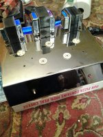
This old amp is made like a car's bumper from the 50s. It is 2/32" thick with a tilted front plate. 3" tall and 13X17 on the top, 15X17 on the bottom. Polished chrome, including the bell ends on the transformers, which I was told that the OPTs were from a Sansui PP EL-34 in a former life. I do know that the air gap is easy to see. It weighs 33 lbs. To heavy to lift with one hand and mess around with a screw driver because I changed the 300Bs isn't something I like to do, so I am putting in the pots. This amp has been sitting quiet for 3 years or so, so I variaced it and decided to put in the pots before wrestling it back in the rack to drive the mid range AMTs. Moving this thing around just isn't fun. I know there are much heavier and I bet they don't have to be tilted back and adjusted under the hood while it is running.
Only Shocked Once,
David Thatcher
I get the center lead of the pot goes to cathode. Maybe. I can't see the schematic while I post, but there are 2 legs for the filament I can't picture in my head how it will work, but once I see the schematic again I will understand.
This old amp is made like a car's bumper from the 50s. It is 2/32" thick with a tilted front plate. 3" tall and 13X17 on the top, 15X17 on the bottom. Polished chrome, including the bell ends on the transformers, which I was told that the OPTs were from a Sansui PP EL-34 in a former life. I do know that the air gap is easy to see. It weighs 33 lbs. To heavy to lift with one hand and mess around with a screw driver because I changed the 300Bs isn't something I like to do, so I am putting in the pots. This amp has been sitting quiet for 3 years or so, so I variaced it and decided to put in the pots before wrestling it back in the rack to drive the mid range AMTs. Moving this thing around just isn't fun. I know there are much heavier and I bet they don't have to be tilted back and adjusted under the hood while it is running.
Only Shocked Once,
David Thatcher
The best you can do for filament-induced hum is to use DC to power the filament.
There are other ways for the hum to enter the circuit, though. If you're hearing 120 Hz hum, it's most likely from B+ ripple. You can get rid of that by regulating the B+ voltage. If you have 60 Hz hum on the output, it's most likely from coupling from the power transformer - either electrical coupling (inductive, most likely) or mechanical coupling. I've seen cases where the mechanical hum of a power transformer created enough vibrations in the top plate of the chassis to cause the 300B to pick it up.
Tom
I have 2 pots because I am putting them in a stereo amp. My Android takes terrible close up pics but I might try my wife's phone and email it to myself so I can post something that is recognizable.
DRT
DRT
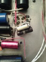
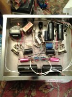
I got some pics to give you an idea of what I am talking about. There has never been a schematic drawn of this amp, but it is a SRPP 6SL7 that could have been built as long ago as 85. There is a socket for a rectifier, but it is SS and Boyle told me that there is no 5V output in the PST. That leads me to believe that this is the second PST that has been in this amp. Much of the wire is hand drawn silver, not my 1st choice, and some of the caps came off during shipping from Oregon when I bought this close to 15 years ago. I put in a bus and it isn't pretty, but I didn't have a soldering station and seldom do this kind of thing.
These pics are just as taken, I haven't done a thing to them so I hope they show what is needed.
Thanks for looking,
David Thatcher
These pics are just as taken, I haven't done a thing to them so I hope they show what is needed.
Thanks for looking,
David Thatcher
Attachments

- Status
- Not open for further replies.
- Home
- Amplifiers
- Tubes / Valves
- Bias for 300B