Although the B+ ripple does cancel it can still produce sidebands around the audio spectral tones due to gain change with plate voltage.
That's exactly the point, and its negation is also true!... "A perfectly balanced push-pull stage will cancel all even harmonic distortion and sum odd harmonic distortion generated within the power stage."
You can even trick the thing to do more by (lightly) unbalancing the phase inverter before it. This is easy to prove with a quick simulation.
Is it not just as simple as to watch a scope image of a music signal in time, and imagine a horizontal axes through the center? You are not watching a mirrored figure although the RMS value of the upper part and the lower part might have the same value at times.
This makes a good read on what causes distortion and how a symmetrical design cancels even harmonics.
http://www.till.com/articles/harmonicdistortion/index.html
If each output valve has a transfer function of f(x) and the phase invertor and transformer are also perfectly balanced then:
fpushpull(x) = f(x) - f(-x)
if f(x) is say x^1.5 like a valve and x = sin(k*t) then some maths or speadsheet will show terms cos and sin(2nkt) will be present where n is an integer.
Last edited:

Another way to illustrate this with simulation: here's an amp I'm thinking of building, maybe one day, for my Jecklin electrostatic headphones.
Nothing fancy, just 2 stages of differential amp. The 1st pic shows the harmonics content of the amp as-is, the 2nd pics shows how H2 can be reduced by adjusting the balance of one of the stages.


Nothing fancy, just 2 stages of differential amp. The 1st pic shows the harmonics content of the amp as-is, the 2nd pics shows how H2 can be reduced by adjusting the balance of one of the stages.
And I find the trick with crossover distortion is to bias it hot enought to get rid of it but not much hotter. Usually, I find if class A power is 1W, crossover distortion will be virtually non-existant
It isn't in phase. What do you think the phase splitter is for?If the signal current through the OPT is in phase in each half
It isn't in phase. What do you think the phase splitter is for?
I think the phase splitter is there to split and invert the signal to drive the tube that is connected to the opposite end of the transformer so that the two currents are in phase through the OPT creating one powerful flux into the secondary.
Phase refers to timing. The word you want is polarity. They're actually not related, but look like it sometimes.
All good fortune,
Chris
All good fortune,
Chris
It's a bit difficult to describe what is going on but it's about the flux direction in each half. If you consider one half has (+) idle current and the other has (-) idle current, then they cancel if both are the same. But when the signals from each tube are applied, the (+) current goes more (+) and the (-) current goes less (-) or in other words more (+) so the direction of the current changes are in phase and so is the direction of the magnetic flux in each half that is added together and its power is transfered to the secondary. The music signals as current and any harmonics riding along with them are copied into the 2 magnetic fluxes in phase and added together for the total power transfered to the secondary.Phase refers to timing. The word you want is polarity. They're actually not related, but look like it sometimes.
All good fortune,
Chris
Last edited:
Kodabmx:
I took some measurements on one of my amps. This is PP UL with 2x6550 on each PP side delivering 120W per channel with 20dB GNF. The supply is 430V and the bias 35ma per tube (servo bias). You are correct in that I can wind the bias down to 10ma and see little degradation in distortion at 500mW. Below this bias level crossover distortion raises rapidly.
However, I can see that in the 1-10W range the distortion gets quite a bit worse as the bias is dropped. This I think is because the amp transitions into class B earlier and this generates its own type of distortion as one tube goes out of conduction. For my amp 35ma seems about right and is still cool.
Hope this is useful.
You can see that in the *Transfer Characteristics": the slopes of the curves, or transconductance, change significantly below 25mA or so.

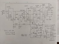
FYI, I build a pair of power amps base on the EICO hf60 circuit with original output and power transformer, I don't like the manual recommend bias at 65ma. I think it may to high for el34, so I modify the bias circuit, add a small signal pnp transistor and few resistors, in this modify the bias voltage will less negative when the output tube cathode 10 ohm dc voltage increase. I had set the bias current to 30ma and no crossover distortion at full power output.
Attachments
I'm not sure I understand what you are trying to say. What is your point with this?Is it not just as simple as to watch a scope image of a music signal in time, and imagine a horizontal axes through the center? You are not watching a mirrored figure although the RMS value of the upper part and the lower part might have the same value at times.
Jan
Well, for 100% cancelling even harmonic distortion generated within the power stage, there exist a few
prerequisites. Besides perfect transformers (without copper loss, without leakage reactance), finals with
identical properties, but most important the input signal must be sinusoidal and perfectly balanced.
Only under these circumstances you find the condition that the (instantaneous value of) plate currents
are in phase opposition to the output load so net flux producing currents and even harmonics cancel out.
Last edited:
Not necessary that signal is pure sine. It works very well with music too.
And it also works with practical, non-ideal transformers or tubes, although cancellation may not be 100%.
If you're technically savvy, you can adjust things like the individual output tube bias to get as close to 100% cancellation as you want.
Jan
And it also works with practical, non-ideal transformers or tubes, although cancellation may not be 100%.
If you're technically savvy, you can adjust things like the individual output tube bias to get as close to 100% cancellation as you want.
Jan
Last edited:
That's a difference between theory and practice then. I was quoting Langford-Smith (RDH4, p573) on the theory of push-pull amplification. It would be interesting to know if the relation of the harmonic distortions changes with the output level or musical signal as they arrive from different origins. H2 could help masking the dominant H3.
Well, Fritz L-S says 'let us assume that the voltage is sinusoidal, that the transformer is ideal, ...' so that he doesn't have to take account of all the inperfections in his calculations, for educational purposes.
He doesn't say that it is a requisite to work, and it isn't.
Jan
He doesn't say that it is a requisite to work, and it isn't.
Jan
BTW Yes, the harmonic spectrum usually does change with signal level. But for the 2nd to mask the 3rd (or reverse) would require that one must be very much stronger than the other, 10's of dBs. That is normally not the case.
Not sure what you mean by music from different origins. You mean different instruments, or different sources?
Jan
Not sure what you mean by music from different origins. You mean different instruments, or different sources?
Jan
- Home
- Amplifiers
- Tubes / Valves
- Bias current