555 bias setting (per manual)
Re #11, Adcom service manual for this first series 555 (download available at Hifiengine) specifies a 3-5 min. warm-up time before setting bias to 16mV in each channel. 'Pretty small for 0.82R resistors. Increasing this to get a clear level of difference may require a four-fold increase in current or more to get a sense of improved sound (at low levels). It becomes a question of the control range of the bias servo circuit and cooling of the output stage as to whether this is going to be a good idea. With such a large amp. I would look at smaller, like 50-100W amplifiers to test this out - or are you feeling lucky? 😉
Re #11, Adcom service manual for this first series 555 (download available at Hifiengine) specifies a 3-5 min. warm-up time before setting bias to 16mV in each channel. 'Pretty small for 0.82R resistors. Increasing this to get a clear level of difference may require a four-fold increase in current or more to get a sense of improved sound (at low levels). It becomes a question of the control range of the bias servo circuit and cooling of the output stage as to whether this is going to be a good idea. With such a large amp. I would look at smaller, like 50-100W amplifiers to test this out - or are you feeling lucky? 😉
I always feel lucky! 🙂
My amplifier is the 3rd build of the GFA-555s. It is not part of the GFA-555IIs but was probably the last build of the GFA-555. Attached is the procedure to set the bias voltage for my amp. Below is the link to the schematic to my amp. The one posted previously was only to give an idea of the circuitry. The two do not differ much but have their differences.
www.civilwarmedicalbooks.com/Adcom/hfe_adcom_gfa-555_schematics.pdf
As you can see from the schematic my amp has VR601 and VR602. That build must have a 10mv bias voltage at TP1 and TP2 (instead of reading off the emitter resister, 0.47R)
I let the amp warm up for 5 mintues or so and adjust. If I go to 10mv as spec'd it is has distortion to the ear. Again no analyzer so have to listen critically which is not the ideal way to achieve the best results but the best I have at this time is my ears and my DMM.
Re #11, Adcom service manual for this first series 555 (download available at Hifiengine) specifies a 3-5 min. warm-up time before setting bias to 16mV in each channel. 'Pretty small for 0.82R resistors. Increasing this to get a clear level of difference may require a four-fold increase in current or more to get a sense of improved sound (at low levels). It becomes a question of the control range of the bias servo circuit and cooling of the output stage as to whether this is going to be a good idea. With such a large amp. I would look at smaller, like 50-100W amplifiers to test this out - or are you feeling lucky? 😉
Attachments
Without professing any expertise with these, the procedure in that note requires part load testing so you need a 100watt dummy load of
8 ohms(not cheap), heavy wire and a steady sinewave source with level control (perhaps the PC) and interconnects to set it up.
That would seem appropriate for replacing output transistors. It must be a proving test.since bias then gets backed off to 10mV again.
That schematic (thanks) fills in the options shown on others with its 0.47R Re's. 10mV across those, still puts the bias current quite low so
a figure around 20mV might be a good place to start testing, assuming it stabilises there, where you set it. This is what matters for the survival
of the amp because nobody posting here has yet suggested what happened when they tried this with an ADCOM 555. If the bias won't stabilise
after you play and then cut signal, there may be a big problem shortly. Still, it should operate this way and be easy to watch while others listen. Enjoy!
GFA555..... Hmmmm, that sounds familiar somehow....
3 to 5 minutes is far too short waiting time.
Bias it as high as you dare, as long as you aren't driving a low impedance load
and can put your hand on the sinks.

3 to 5 minutes is far too short waiting time.
Bias it as high as you dare, as long as you aren't driving a low impedance load
and can put your hand on the sinks.
As I said, these are not quite the same thing. Constant gm should be the aim; this ensures low distortion. This is likely to provide constant output Z too, but that will be affected by feedback.
I do agree but I tend to think of the output stage as a seperate entity. This way when you apply feedback, your not relying on the feedback to 'correct' the problems within the output stage. True that the driver stage, steered by the feedback loop has an effect and no class AB output stage will be perfect, but IMO, it is better to optimize linearity of each stage before feedback is applied. The less the closed loop has to deal with the better the situation. The point is, there is an optimal bias and there are specific reasons why there is an optimal bias.🙂
Last edited:
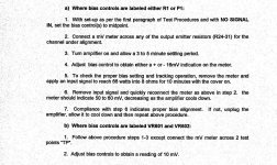
I interpret the GFA set up as a rising bias voltage with rising output temperature.
With the amplifier relatively cool (3 to 5 minutes) after start up with no signal, the bias voltage (Vre) is set to 10mV.
Without changing anything, they tell us to apply signal ans run the amp into load and let it get hot.
Remove the signal and while still hot, recheck the Vre. It should have risen to 60mVre. They further tell us that as the amp cools the Vre returns slowly towards it's cool setting.
If my interpretation is correct, then we have an under compensated tempco and when the amp runs warm the Vre is higher than 10mV. Maybe in typical operating conditions it is around 25mVre +-5mV.
You are correct. The amp is a under compensated tempco design. It is my experience that the amp operates exactly as you have suggested. After setting bias to 10mv when warm the amp runs higher bias voltage as temp rises.
Good observation and again it operates just as you have suggested.
I raised the bias voltage to 15mv this afternoon and ran it more than warm. It stabilized well. Adjusted it to 20mv and ran it to hot when placing a hand to the heat sinks. The amp did not stabilize after the cooling period. It came to almost 15mv on the right channel but went to 30mv on the left channel and stayed hot to the touch. Turned the amp off and let it cool. Back on to warm and adjust to 10mv. Testing now.
I interpret the GFA set up as a rising bias voltage with rising output temperature.
With the amplifier relatively cool (3 to 5 minutes) after start up with no signal, the bias voltage (Vre) is set to 10mV.
Without changing anything, they tell us to apply signal ans run the amp into load and let it get hot.
Remove the signal and while still hot, recheck the Vre. It should have risen to 60mVre. They further tell us that as the amp cools the Vre returns slowly towards it's cool setting.
If my interpretation is correct, then we have an under compensated tempco and when the amp runs warm the Vre is higher than 10mV. Maybe in typical operating conditions it is around 25mVre +-5mV.
I agree with AndrewT; you need a tad more temp compensation. Do you know the topology of the bias generator? Sometimes just a few series connected diodes can do the trick.
Hugh
Hugh
The schematic is in post 22 but it's not easily seen where the compensation is applied. Being snail-speed, it's not likely positioned near the heatsink(s) either.
I have the bias setting at 10mv and the amp stabilizes at that level This after running it at the recommended level for 15 minutes at which the heat sinks got hot  but I could still lay my hand there for a short time. After cool down it settled back down to 10mv. Again this is the factory specified setting for this build of 555 and I think I will leave it. I did find that the right side trim pot has a issue with staying set and am replacing both sides. They do seem a little cheapo from the manufacturer.
So I did raise the bias voltage 4mv to 10mv and the amp sounds just as good as it did at 6mv. However I do realize that it has a better shot of staying in Class A mode at the higher level. I appreciate you and all others who has enlightened me a bit on the amp design. I learned a few things that I did not expect!
but I could still lay my hand there for a short time. After cool down it settled back down to 10mv. Again this is the factory specified setting for this build of 555 and I think I will leave it. I did find that the right side trim pot has a issue with staying set and am replacing both sides. They do seem a little cheapo from the manufacturer. So I did raise the bias voltage 4mv to 10mv and the amp sounds just as good as it did at 6mv. However I do realize that it has a better shot of staying in Class A mode at the higher level. I appreciate you and all others who has enlightened me a bit on the amp design. I learned a few things that I did not expect!
GFA555..... Hmmmm, that sounds familiar somehow....
3 to 5 minutes is far too short waiting time.
Bias it as high as you dare, as long as you aren't driving a low impedance load
and can put your hand on the sinks.
Pre,
you show in post22 the extract from the gfa set up procedure.
you describe in post30
Where do you get the claim?
you show in post22 the extract from the gfa set up procedure.
you describe in post30
a different procedure .I have the bias setting at 10mv and the amp stabilizes at that level This after running it at the recommended level for 15 minutes at which the heat sinks got hot but I could still lay my hand there for a short time. After cool down it settled back down to 10mv.
Where do you get the claim?
Again this is the factory specified setting for this build of 555
Last edited:
- Status
- Not open for further replies.
- Home
- Amplifiers
- Solid State
- Bias Current Class AB Amplifier - More Always Better?