Hello everyone. I am having a discussion with some friends over adjusting the bias on my amplifier. First off I will state that it is a Adcom GFA-555 which is a class AB amplifier. It is a good sounding amp, not great but well enough for now. I have been tweaking it all along for a few months and am happy with it.
Originally adjusted the bias according to the manual but have not been satisfied with the sound. Forgive me as I do not have a distortion analyzer so I have been adjusting the bias by ear and using my DMM.
Long story short I adjust the bias down below factory specified levels. From 10mv to 6mv. I paid close attention to sound using one track to monitor the sonic changes. At 6mv the small amount of distortion left and I am left with a near perfect sounding amp for that design.
Now here is my question. My friends and I are politely disagreeing over the fact that I can decrease bias current to eliminate distortion. A few articles have been given by my friends as information and will be listed below as proof that you can only increase bias current to eliminate it. My opinion and experience here with my amp is that you can decrease bias to eliminate distortion and that it depends on the design of the amp.
I would like to hear your thoughts on decreasing bias current to eliminate distortion.
http://www.passdiy.com/pdf/leaving_class_a.pdf
https://passlabs.com/articles/the-sweet-spot
Is the adcom a quasi complementary output stage or a fully complementary EF output stage, or a fully complementary CFP (common emitter) output stage?
All of these need different biasing to minimise crossover distortion.
All of these will have different dynamic bias errors that will suit different cold or hot bias adjustments.
All of these need different biasing to minimise crossover distortion.
All of these will have different dynamic bias errors that will suit different cold or hot bias adjustments.
Better you make the switch turn on for hight bias and lower bias and hear by ear.
offcouse if it is not good why they make class A amp???
disscuss why -->no. because device (trans,..mos,fet,jfet..) need have some voltage to work (material ,..) and even same type,name it was still diff ( matching it you will see).
end May be hope in future they will make new device which working with lower lower control Voltage (0,00000..mV) and verry verry fast frequency transient .
HA HA HA.
The Adcom is a quasi complementary output stage. Schematic attached:
Is the adcom a quasi complementary output stage or a fully complementary EF output stage, or a fully complementary CFP (common emitter) output stage?
All of these need different biasing to minimise crossover distortion.
All of these will have different dynamic bias errors that will suit different cold or hot bias adjustments.
Attachments
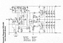
What? thats surely a full complementary output stage. quasi is all one type such as all npn or all pnp, but that has npn high side and pnp low side output stage = full complementary.
Oops! Sorry. Yes thank you for the clarification.
What? thats surely a full complementary output stage. quasi is all one type such as all npn or all pnp, but that has npn high side and pnp low side output stage = full complementary.
Darlingtons generally need a fairly high quiescent current. Complementary pairs usually need a low current. I can't imagine how you set a quasi-, as that has Darlington one side and CFP the other.
6mV is a voltage, so over what resistance is this measured? Bear in mind that the current may be set a bit high, so heating up can drop it without creating problems.
6mV is a voltage, so over what resistance is this measured? Bear in mind that the current may be set a bit high, so heating up can drop it without creating problems.
That I have not figured but understand why you are asking. Correct that 6mv is voltage and does not reflect the current until resistance is figured. I will get that number for you.
6mV is a voltage, so over what resistance is this measured? Bear in mind that the current may be set a bit high, so heating up can drop it without creating problems.
There’s usually an optimum bias point that produces the lowest distortion in a given AB design. Go higher or lower and things usually get worse. It’s all documented ad-nauseam in various books. Now what you perceive as lowest and what an instrument actually reads as lowest may not necessarily be the same thing though.
I understand your statement fully. It would be nice to have a distortion analyzer handy. As I progress in the hobby of diy, tools will surely come my way. However now I am one of those who feels lucky to have decent gear and a tad of diy skills. Thank you for the reply. 🙂
There’s usually an optimum bias point that produces the lowest distortion in a given AB design. Go higher or lower and things usually get worse. It’s all documented ad-nauseam in various books. Now what you perceive as lowest and what an instrument actually reads as lowest may not necessarily be the same thing though.
There’s usually an optimum bias point that produces the lowest distortion in a given AB design. Go higher or lower and things usually get worse. It’s all documented ad-nauseam in various books. Now what you perceive as lowest and what an instrument actually reads as lowest may not necessarily be the same thing though.
Agreed. It has to do with output impedance and how much is being contributed to the output from each half, NPN and PNP. Push pull class A maintains a constant output Z but is inefficient. Too little bias in class AB results in an increase of output Z at the zero current crossing causing cross-over distortion. Too much bias results in the output transistors both contributing to the output Z in paralell, causing what is known as Gm doubling. It produces crossover distortion like components as well. There is a happy medium and it depends on the amplifier and the load it is intended to drive. I suspect the designers of this amp know this and have calculated and measured the proper bias.
Thank you CBS for the information. I am also sure the designer of the amp has documented the correct bias adjustment in the manual. My opinion is that over time a 25 year old amp would have components that are not as new and that explained why my drop of 4mv bias voltage (from 10mv to 6mv) gave me an improvement in the amp. Again, forgive me as all my evaluations are made through objective listening which is probably frowned upon in this forum.
C-town to the West of K-town.
C-town to the West of K-town.
Almost. More a case of transconductance gm. Of course, these two concepts are related but they are not quite the same thing.CBS240 said:It has to do with output impedance
I would be surprised if this is the case, unless some output stage resistors have significantly changed their value. Check them.PreCD said:My opinion is that over time a 25 year old amp would have components that are not as new and that explained why my drop of 4mv bias voltage (from 10mv to 6mv) gave me an improvement in the amp.
My opinion is that over time a 25 year old amp would have components that are not as new and that explained why my drop of 4mv bias voltage (from 10mv to 6mv) gave me an improvement in the amp.
Apart from the bias issue it would not hurt to check all electrolytic capacitors in your amp, and maybe a good idea is to replace them by fresh ones anyway.
Electrolytics don't last for ever; some years ago I bought a 30 years or so old Yamaha B2 amp where all electrolytics were worn out; actually a miracle that it produced music... It had a complete capacitor replacement and sounded like new since.
That was the 1st set of components that came to mind. To be honest this scenario is getting out of hand. I am grateful for the fact that you guys are attacking this from a functionality standpoint. It would be the only way to go if I were having trouble. However the amp is sounding the best that it has since I adjusted the bias voltage.
My original question was geared more to the design of my amp and your experiences with such designs in adjusting bias voltage. And secondly how my dropping bias voltage from the specified 10mv to 6mv improved the sound when the articles my friends posted states that higher bias current improves distortion. Not maybe improved the sound but definitely improved the sound in relation to distortion.
Again I am appreciative for all your inputs but at this point I feel like I am just wasting a lot of people's time on this. You all are great!
I would be surprised if this is the case, unless some output stage resistors have significantly changed their value. Check them.
Agreed! Attacking the electrolytics was the 1st line of business when I received the amp late last year. Even the filter caps which killed a light hum in one channel and dropped my DC offset by 20mv.
Apart from the bias issue it would not hurt to check all electrolytic capacitors in your amp, and maybe a good idea is to replace them by fresh ones anyway.
When reading about bias you need to be aware that some people prefer 'first watt Class A' bias' - they deliberately use a much higher bias current than 'optimum'. The idea is that the changeover point when one output side stops conducting is moved well away from the signal zero crossing to two roughly equally spaced either side. The result may be less distortion for small signals but more distortion for bigger signals. Most listening is done with small signals, so on balance they feel this is an advantage.
If we assume that the 'correct' quiescent current for some circuit is 15mA, then 10-20mA should be fine (the NFB will sort out small wiggles). 50-100mA would increase crossover distortion because of gm-doubling. 250mA or more would give 'first watt' conditions, although you might need bigger heatsinks. I think the story is that you either need about the 'right' amount, or a huge lot more; in between distortion is worse (yet I suspect this is where some people misadjust their amplifiers).
If we assume that the 'correct' quiescent current for some circuit is 15mA, then 10-20mA should be fine (the NFB will sort out small wiggles). 50-100mA would increase crossover distortion because of gm-doubling. 250mA or more would give 'first watt' conditions, although you might need bigger heatsinks. I think the story is that you either need about the 'right' amount, or a huge lot more; in between distortion is worse (yet I suspect this is where some people misadjust their amplifiers).
A typical starting point, when you don't have the manual or the service tech alongside for advice, is to look at the emitter resistors, the big ones in the emitter leads of the output transistors, R21-28, I think. These will give an idea of how much mV you should read across them (hence bias current) for any transistor in series. Do these read O,22R or is that 0.82R?
I would expect them to be a more or less standard 0.22R, in which case a typical bias setting range would be 15 -25mV across each resistor (they will be the same as they are in series or parallel). However, if those Re's are different, I'd think about that first. When you do set a current, monitor it to be sure that warming is slow and steady.
Have a close look at #7 http://www.diyaudio.com/forums/solid-state/101726-adcom-gfa-555-bias.html
Last edited:
Almost. More a case of transconductance gm. Of course, these two concepts are related but they are not quite the same thing.
The goal is to achieve a constant output Z for the whole range of operation, thus a constant Gm, because any change in Zout will reflect a change in voltage gain of the output stage. IOW, ideally Gm vs Ic should have no slope or a vertical line, from +Vcc to -Vcc. This is virtually impossible so we comprimise with the use of emitter resistors and bias current setting so that we can reduce the variation from Av=1 (ideally) of the output stage emitter follower circuit that is related to the inconsistancy of Gm that occurs at the zero current crossing. BJT's have very steep Gm vs Ic slope above a few 10's of mA. Mosfets are not the same. With Mofets the bias setting is less critical, as long as it is within a suitable range. BJT's need more acuracy.
If you connected one scope channel to the amplifier output and the other to the VAS output, you can compare the two signals as you adjust bias. When the outputs are under bias, the slope of the signal from the VAS will become steeper in order to make up for the drop in Gm (increase in output Z) at the zero current crossing. The result is more high order distortion products being created by the IPS and VAS. This is not an ideal situation because the BW of the global loop is limited.
Last edited:
As I said, these are not quite the same thing. Constant gm should be the aim; this ensures low distortion. This is likely to provide constant output Z too, but that will be affected by feedback.The goal is to achieve a constant output Z for the whole range of operation, thus a constant Gm,
BJTs have a very constant gm vs Ic relationship over a wide range of currents, but output stages complicate this, whether Darlington or CFP, because of the interaction between driver and output.
- Status
- Not open for further replies.
- Home
- Amplifiers
- Solid State
- Bias Current Class AB Amplifier - More Always Better?