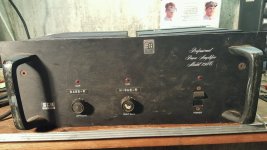
Just acquired this amp last night for a project. Was told that the amp had a low power symptom but to no surprise it pops the combination fuse breaker and on off switch. It was powered up using a light bulb on the power cord. Bulb was bright.
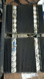
The right channel has newer outputs MJ15023/MJ15022. Appears to be an older replacement. Doesn't appear to have anything smoked.
Advice?
The right channel has newer outputs MJ15023/MJ15022. Appears to be an older replacement. Doesn't appear to have anything smoked.
Advice?
Attachments
Last edited:
The round phenolic connectors on the power boards just pull apart...
any tricks getting them apart? Or just use large flat screwdriver and carefully pry.
Disconnecting these from the power boards should isolate fault to power supply section or power boards?
any tricks getting them apart? Or just use large flat screwdriver and carefully pry.
Disconnecting these from the power boards should isolate fault to power supply section or power boards?
Hi Bob,
You're talking about the thermal switches? Just pull them apart and wiggle side to side a little. They can be stubborn to remove, but you just have to work at it. Avoid up and down motion as that can break the switch.
If you unplug the octal connector on the module you have isolated the supply to the chassis and whatever module is still plugged in. You can run the amplifier without one channel with no ill effects. Just make sure the air is forced through the remaining heat sink if you want to party with that one channel.
I really like working on these amps. If you are careful and match things, they can sound extremely good. The op amp is an LM318, I can't remember if it is used in feed forward mode or not.
-Chris
You're talking about the thermal switches? Just pull them apart and wiggle side to side a little. They can be stubborn to remove, but you just have to work at it. Avoid up and down motion as that can break the switch.
Yes.Or just use large flat screwdriver and carefully pry.
If you unplug the octal connector on the module you have isolated the supply to the chassis and whatever module is still plugged in. You can run the amplifier without one channel with no ill effects. Just make sure the air is forced through the remaining heat sink if you want to party with that one channel.
I really like working on these amps. If you are careful and match things, they can sound extremely good. The op amp is an LM318, I can't remember if it is used in feed forward mode or not.
-Chris
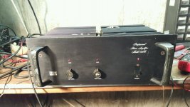
No need to fret it was popping the breaker because it had the light bulb on it. Disconnected both power modules inspected, everything looked good. Powered up psu on light bulb it was good. Connected the left module on light bulb it was good, disconnected and connected right module good on light bulb, no hard shorts. Connected both modules brought it up without light bulb bingo everything up and running. Sounds great. Pretty happy with this at $80.00.
Attachments
Hi Bob,
Not bad for $80. You should hear one after the parts have been matched and the amp detailed. They can sound pretty darned nice, but no one would know it by the way they look. I did a bunch for a company, then the employees as they sold them off. Did one for one guy and the next thing I knew, there was a mini rush on having them "detailed". They can sound much better than they have a right to said one fella.
-Chris
Okay...I got all wrapped up with the fact that the amp has two different revision level power boards. Decided to live with that...shouldn't be an issue. At sometime the left channel board was removed(REV C) and replaced with a repaired rev E board. This board has newer outputs and has obvious indication of blown resistors and circuitry that was either replaced or repaired. Putting it on the scope shows an overshoot (or ringing) issue. Have checked and found the input signal is okay at the input of the opamp. At the first predriver the symptom is evident.
I purchased a 30pF (C6) on the feedback circuit have not checked to see if it improves this issue.
I purchased a 30pF (C6) on the feedback circuit have not checked to see if it improves this issue.
Attachments
Last edited:
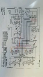
Voltage divider R6/R2 applies the correct amount of feedback to the noninverting input(pin 3) of opamp. The overshoot appears at the first predrivers Q1 and Q2. Could the feedback circuit be the cause of this. Could tweaking C6 (30pF) affect this? Feedback on schematic is green.
Attachments

Hi Bob,
Can you describe the problem you're having? It's like we were dropped into the middle of a conversation.
Maybe you should start a new thread on this.
-Chris
Can you describe the problem you're having? It's like we were dropped into the middle of a conversation.
Maybe you should start a new thread on this.
-Chris
Hi rfitts46
1. Verify the problem
2. If the same as before unplug one channel and try power on again.
3. Try the other channel module and try power on again. This may narrow the problem to one channel.
4. The C11 & C12 should be replaced. If they are removed the amp should not POP when turned ON.
I do know all about the BGW’s, just look @ the schematic.
Duke
Chris, I tagged off of this thread from 2016 because this has been present since I originally got it. There was an image of the overshoot from 2016. The amp operates as it should. If eliminating or reducing the overshoot is not too difficult thought I would look at it.
Maybe I should not be concerned with it?
Maybe I should not be concerned with it?
Last edited:
Hi Bob,
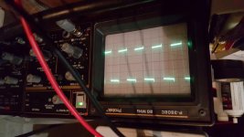
Okay, I see it now. I wouldn't worry about it. I haven't looked, but this might just be feed forward compensation. Look up the LM318 datasheet to confirm the hookup. Given that this is the leading edge of a square wave, I wouldn't worry about it. I've never tested a BGW 750 using a square wave before. It could even be something really odd with the test setup. I take it the generator doesn't have any peaking on the leading edge? It might be a lot narrower pulse and the amp is just stretching that very fast pulse.
-Chris
Hi Duke,
As long as those capacitors are roughly equal in value there shouldn't be a problem. That's assuming they are in good condition of course.
-Chris
As long as those capacitors are roughly equal in value there shouldn't be a problem. That's assuming they are in good condition of course.
-Chris
image was of a 5V output with a 1V 400hz pulse on the input.
no evidence of overshoot on the other channel.
pulse is square going into opamp
pulse has overshoot after opamp going into predrivers.
If the overshoot is created in the driver/output circuit would it then be
present on the feedback signal being fed to pin 3?
no evidence of overshoot on the other channel.
pulse is square going into opamp
pulse has overshoot after opamp going into predrivers.
If the overshoot is created in the driver/output circuit would it then be
present on the feedback signal being fed to pin 3?
Hi Bob,
Yes, it should be. If it is being rolled off by something, that would do it. Often you can't probe the inputs directly. Try using a 100R resistor in series with your probe tip and monitor the output of the amplifier as well.
-Chris
Yes, it should be. If it is being rolled off by something, that would do it. Often you can't probe the inputs directly. Try using a 100R resistor in series with your probe tip and monitor the output of the amplifier as well.
-Chris
Hi All
I’m confused, is the AC POWER SWITCH still pumping upon turn ON (false tripping)?
If C11 or C12 is the 20uf/100v cap is leaking the outputs can cross conduct during turn ON. This will trip the magnetic circuit breaker. No sound would be heard as the delay relay has not energized yet. The big electrolytic (leakage) can also cause the breaker to trip. If disconnecting both caps stops the problem then replace both of them.
Is the OVERSHOOT on the module with the newer output devices? If so the faster outputs need additional compensation.
I was the VP Engineering & Mfg @ BGW 1974-86
Duke

Hi Duke,
That must have been a fun job back then. You lived through the most interesting times for amplifier development. Probably the most frustrating times as well.
I used to rebuild many 750B and 750C in the mid 80`s to earlier 90`s. I always thought they were well designed, but serviced poorly. No one followed the directions in the service manual (which I got from BGW early on). I also did a lot of Carver, being Canadian factory warranty in the 90`s.
I guess you would want Bob to replace those two capacitors first, right? I don't think he has a good capacitor checker.
-Chris
Duke, you sure have good credentials for knowing your way around this BGW 750.
Duke the original problem experienced at initial power up after purchase back in 2016 was my using a dim light bulb and trying to power the amp up. I experienced similar issue trying to power up Crown DC300's. it seemed the outputs wanted to swing to rail voltage....stopped powering these large amps or anything with protect circuitry up with DLB ......I generally will use a variac and an ampmeter. with better results Anyway using the variac stopped the tripping at power up.
there was a clip light coming on at initial power ups immediately after acquisition. I convinced myself that playing with the relay fixed that problem but it came back after it sat for a long period of time. Tinkered on the inside and it went away again.
during inspection I noted the amp must have had rev C boards from the factory and somewhere along the way a rev E board with newer outputs got installed.
during some basic input to output checks using signal generator and oscope the overshoot was observed on the channel with the rev E board with the newer outputs.
I am a mechanical engineer probably should have studied EE...I really love learning about amplifier circuits.
I first saw the overshoot at the 8 ohm load at the output of the amp.
stuck a probe at the input of the opamp...signal was clear as a whistle. stuck probe on first predrivers after opamp and the overshoot appeared there.
the amp ended up going to my brother and at some point I was made aware that he wasn't using it....then my brother passed Jan 2019. the amp ended coming back to me. since getting it back...the clip light is back on.... the random clip light coming on was a leaky xistor in the clipping circuit. took a bit of tinkering for me to figure it out.
then put in a new fan to quiet the noisy fan.
it's back up in the rack....does have alot of headroom...would like to ensure the overshoot isn't compromising the high freq.
so when you say the faster outputs need more compensation...i believe that's where I was heading...though remember I am a ME.
so I was thinking of tweaking the 30pF that's part of the RC circuit on the feedback circuit....which I don't mind doing but I prefer somebody to have my back when playing with the feedback circuit.
Listening.......what are your suggestions?
Chris, which two capacitors are you talking about? All the standard capacitor replacements got done back in 2016.
The 30pF capacitor on the feedback RC circuit was replaced with a new 30pF....no change on the overshoot.
I think the value needs to be tweaked to see if any improvement on the overshoot occurs.
The 30pF capacitor on the feedback RC circuit was replaced with a new 30pF....no change on the overshoot.
I think the value needs to be tweaked to see if any improvement on the overshoot occurs.
- Home
- Amplifiers
- Solid State
- BGW 750C popping the combination fuse on/off switch