100mA easily is not true for a capacitor input filter loading a transformer.10VA / 48V = 0.2083 A => 100ma draw easily
BTW, I was talking about 24V AC + 9V AC 10VA transformer (post #28 - final preamp's schematic)
~100mA is the maximum continuous rating from a 10VA 48Vac transformer.
At this current the transformer will be running hot.
It may be hotter than the maximum temperature rating of the manufacturer.
Where do you suggest he buys a 24Vac + 9Vac ~10VA transformer?
I run this preamp with two transformers (3.9VA each) and they are absolutely cool. Stop seeding paranoia.100mA easily is not true for a capacitor input filter loading a transformer.
~100mA is the maximum continuous rating from a 10VA 48Vac transformer.
At this current the transformer will be running hot.
I suppose the schematic (post #28) is a suggestion enough.Where do you suggest he buys a 24Vac + 9Vac ~10VA transformer?
To avoid possible misunderstanding, I should be more specific about transformer and PS. The fact is that whenever there is a precise explanation but longer than 5 sentences, there will be someone who didn't read it carefully enough or simple doesn't understand it and we have an instant controversy.
To avoid that, I say:
- readers who understand the schematic and have some knowledge and experience will know what to do;
- the rest of the crew take the 30VA transformer or 50VA or whatever makes you feel good
I made this preamp, it works nicely for me and for guys who built it, I'm sharing the project here - that's all I can do. I can't make anyone learn anything and I can't pet anyone's vanity.
Dear juma, don't get tempted😱 everyone is just sharing their thought
i really very appreciate and thanks your hardwork for sharing this and i like it very much... you are one of the man in my admire list🙂
i really very appreciate and thanks your hardwork for sharing this and i like it very much... you are one of the man in my admire list🙂
juma,
Let me add my thanks for your contributions also. It's much appreciated, even if I am a slow learner...
Cheers
Nigel
Let me add my thanks for your contributions also. It's much appreciated, even if I am a slow learner...
Cheers
Nigel
Schro20, Bappe & Ucciopino, A couple of months back you expressed interest in joining a GB for Juma's pcb. I have had your names saved on a list. The GB is progressing and I am about to the closed the buy. Please confirm if still intend to participate either via PM or by posting to the GB thread. The GB is here http://www.diyaudio.com/forums/group-buys/158425-gb-bf862-preamp-jumas-work-2.html#post2053799
Hi npapp,
please remove my nick from that GB - I know that you mean it as a recognition, but someone might think that I have some financial interest in that GB which is not the case.
Thank you 🙂
please remove my nick from that GB - I know that you mean it as a recognition, but someone might think that I have some financial interest in that GB which is not the case.
Thank you 🙂
Hi npapp,
please remove my nick from that GB - I know that you mean it as a recognition, but someone might think that I have some financial interest in that GB which is not the case.
Thank you 🙂
Hi Juma, Sorry if my naming made you uneasy. Of course this was only meant for recognition since this was your design. I don't know if there is a way to change the name but maybe one of the moderators can help. I will ask and see how to best resolve this issue. In the meantime, I can clarify that you are not a partner in this group buy. Also, there is no financial gain planned for myself. Any excess funds will go to forum in the form of a donation when the GB is complete.
Nick
Name changed
Mark
Hi Guys,
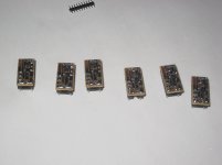
No-one responded to my post #119 about redoing the output buffer boards, so I decided to go ahead and do it anyhow... Photo attached of the six boards ready to be installed in DIP-16 sockets.
"Six?" you may ask... Don't worry, I haven't suddenly decided to tri-amp the system 😀 I only need four for Big Greenie, but making six at the same time is little more work than doing four, and I decided I'd like to have a couple of spares. This way I'm covered if any of them is duff, and if all are OK then either I build another preamp, or some lucky friend gets one...
Each of the boards contains the basic preamp circuit minus decoupling and output caps. (PSU is obviously not on it...)
Next couple of evenings I intend to pull the main board, and replace the larger output buffers, for all the reasons explained in #119. It should also allow for a much cleaner p2p layout on the bottom, which has to be a good thing...
Cheers
Nigel
Attachments
i mistakenly bought some 0.125w resistors, do them work in this design?
Or only quarter watt is suppose to be ideal...
Or only quarter watt is suppose to be ideal...
hi juma.Can i use my 2sk170bl grades which have 12ma idss? And what value pot should i use for best result?and other question where is the place of pot?input or output of the preamp? thank you
...
Can i use my 2sk170bl grades which have 12ma idss?
And what value pot should i use for best result?
where is the place of pot?...
Yes
10k-20k
input
i mistakenly bought some 0.125w resistors, do them work in this design?
Or only quarter watt is suppose to be ideal...
Hi chchyong89,
I am using 1/8 W resistors (SMD) in the preamp section without problems. The resistors I am using in the PSU sections are larger, but I expect 1/8 would be OK too, although to be sure the currents and power and so forth would have to be calculated.
Cheers
Nigel
oh thanks a lot njepitt, i am still learning to walk 😛
however, can anyone provide me the lib for IRF9620 and irfp044?
.model xxxxxxxxxxxxxxxxx😱
i have tried to google around but can't find any result🙁
however, can anyone provide me the lib for IRF9620 and irfp044?
.model xxxxxxxxxxxxxxxxx😱
i have tried to google around but can't find any result🙁
where to place my relay attenuator?
the sheet of my twisted pear "yoshua tree" relais attenuator says:
"The kit's input impedance varies between 2.2K and 10K, with a fixed output impedance of 750R"
Can anyone say if it´s still best to place it at the input?
tnx
stefan
the sheet of my twisted pear "yoshua tree" relais attenuator says:
"The kit's input impedance varies between 2.2K and 10K, with a fixed output impedance of 750R"
Can anyone say if it´s still best to place it at the input?
tnx
stefan
oh thanks a lot njepitt, i am still learning to walk 😛
however, can anyone provide me the lib for IRF9620 and irfp044?
.model xxxxxxxxxxxxxxxxx😱
i have tried to google around but can't find any result🙁
Do you mean the datasheets? If so, they can be found here
http://www.datasheetcatalog.org/datasheet/fairchild/IRF9620.pdf
and here:
http://www.ram-e-shop.com/ds/tr/IRFP044.pdf
Hope that helps.
CHeers
Nigel
Do you mean the datasheets? If so, they can be found here
http://www.datasheetcatalog.org/datasheet/fairchild/IRF9620.pdf
and here:
http://www.ram-e-shop.com/ds/tr/IRFP044.pdf
Hope that helps.
CHeers
Nigel
😱 i wish to simulate this circuit on computer, but LTspice come w/o both of this mosfet model, so i am searching around it's library to add on the software.
- Home
- Amplifiers
- Pass Labs
- BF862 Preamp