....but - I'm not expecting that you are going to hear too much difference
Nor am I, if I'm honest, but it should be fun, and it won't cost much, so why not give it a go? And if it only shows that there's no difference between PRP and the cheapo Brazilian no-names I'm using then that's better still, right? 😀
And I've already learned something from you and juma this evening, so that's good too...
Regards
Nigel
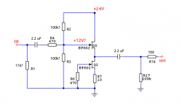
Those who have already built B1 and just need some additional gain, can add just the gain stage (and the PSU) in the existing box. Coupling cap (C3) is not needed if your B1 already has one at the input.
Hello
Does this gain stage would change the sound of the B1 ?
Thank
Gaetan
Attachments
Last edited:
It's very easy to test it.
I like BF862 better than 2SK170 - you might have different preferences...
I like BF862 better than 2SK170 - you might have different preferences...
Last edited:
I found this thread interesting...
But of course I have a question! =)
I am in need of a few buffers, and I don't have enough 2SK170s to make normal B1s but the BF862 are infinitely more available. I, however, only have a positive rail 24V PSU in my amps:
Would the buffer part of the preamp work without the negative PSU? Here you say that the gain part absolutely needs negative supply but not if the same is true for the buffer part.
EDIT: Not sure if it makes a difference but I don't need the full 6V output, 2V would be enough for me.
Last edited:
Yes...Would the buffer part of the preamp work without the negative PSU?..
Nice!
So I have a bunch of more questions:
First about Idss, is there a specific Idss range this circuit is optimized for?
And lets see if I've understood this:
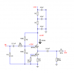
First I chop off the gain stage. The output I want to buffer is that from a Jensen JT-11P-1 with ideal load of 10k. So I set R1 to 11k and R3 to 100k for 10k input impedance.
The next step I'm not sure about but I think I want 1/2 vcc => 12V at the upper Jfet gate so I set R2 to 100k too.
And then after the Jfets, do I just chop off the negative supply part like this or do I need to do something more?
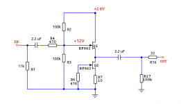
And I think R16 controls output impedance, my amp has 10k input impedance so I don't need as low as 33. I might as well throw on 100 as I have lots of those lying around =)
Attachments
Idss = 10 - 20 mA
Sch OK
R16 = 15 - 33 R
Nice, and 33R on R16 it is.
Thanks for the help!

Now I just need to buy a few matched BF862s or say 50 and match myself 🙂
Attachments
Yes, just take care that your 24V power supply is perfectly clean because it's connected directly to JFETs gate. Otherwise, you'd better use B1 schematic...
Yes, just take care that your 24V power supply is perfectly clean because it's connected directly to JFETs gate. Otherwise, you'd better use B1 schematic...
Yup, in the actual circuit i'll probably clean the rail a bit before I connect it to the buffers.
Also, if I understand correctly the buffer will have a bias current of ~ 15-20mA?
My rails should be pretty clean, I'm using a SMPS with extra CRCRC filtering. I'll probably chuck at least a local cap close to the Jfets on each buffer board or I'll go all out and build another small CRCRC on it. With the SMPS I can get away with small caps and I need to burn 2V to get my rails to 24V anyway. But considering that my main power is clean enough that the ripple is below the noise of my scope it's probably enough to just add a cap =)
Attachments
Last edited:
OK, but be aware that any noise you might or might not hear comes from the rails.Yup, in the actual circuit i'll probably clean the rail a bit before I connect it to the buffers.
The current through the buffer will be determined by CCS (Q2) ie. its Idss minus degeneration caused by its Source resistor (R7).Also, if I understand correctly the buffer will have a bias current of ~ 15-20mA?
bf862 are sot23.
They don't have a large dissipation.
24V supply roughly equates to 12Vds on each jFET.
10mA of Id results in 120mW and will be very warm.
20mA of Id results in 240mW and will be HOT !
The 10r for R7 will significantly reduce Id.
You should take some measurements as you increase the supply voltage.
Check dissipation at Vcc = 12V, i.e. Vds=~6V.
Do you need R1=11k?
It sets the input impedance very low.
It could be anywhere from 1K to 10M depending on what your Source wants/needs to see.
Last edited:
Alright.OK, but be aware that any noise you might or might not hear comes from the rails.
The current through the buffer will be determined by CCS (Q2) ie. its Idss minus degeneration caused by its Source resistor (R7).
I looked up on cap sizes and for future portability I'll probably do a crcrc with 1mF caps. They were so small anyway and then if I in the future want to use a normal transformer I won't have to add more rail smoothing. Or I'll just throw on 24V voltage regulator as the current is so low anyway.
Last edited:
Not if you keep its Pd under 150mWwill the BF862s require heatsinking?
Also another question, will the BF862s require heatsinking?
None of those I've used have failed, but they do run hot. You could "pour" copper to help dissipate heat.
NXP tell us that the gate lead is the main exit route for heat from the junction.
I did not see this info in other manufacturers' datasheets.
Pmax for these bf862 seems to vary between manufacturers. I have seen 225mW to 300mW.
150mW dissipation in a 225mW device seems high to me.
I did not see this info in other manufacturers' datasheets.
Pmax for these bf862 seems to vary between manufacturers. I have seen 225mW to 300mW.
150mW dissipation in a 225mW device seems high to me.
Didiet,
compare to a To3 power device of 250W rating, i.e. MJ15003/4 and MJ29113/4
I would not run those at a quiescent value of 150W, even if I could keep the heatsink at around 25°C
Now divide the powers by a thousand and apply to the jFET.
The main purpose of the dual To92 is to maintain a close matching temperature of the two devices.
Cooling is secondary, basically because the junction is buried inside an insulating casing.
Last edited:
- Home
- Amplifiers
- Pass Labs
- BF862 Preamp