My take on this issue is that it is not too important to bother with.
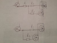
More resistor means more money and probably noise. But may be easier to match between P and N channels by changing only the first resistor in paralleled mosfets.
I prefer to bother with as close as possible track. The gate stopper right on the gate pin. Even the "correct" value of the resistor is more important to bother with (which I still don't really care anyway)
This is wisdom of this Forum................. The gate stopper right on the gate pin. ..........
A RC zero is much more effective in controlling the active resonance circuit, that being the mosfet and it's internal components. The combination of gate stopper resistor and a gate Zobel from gate to drain along with local high frequency decoupling such as a 100nf film cap from drain to GND will prevent mosfet instability regarding transient output current. As stated these components should be as close to the device as possible, as should any Vgs Zener protection. 🙂
IOW niether of those drawings is optimal.
IOW niether of those drawings is optimal.
Last edited:
- Status
- Not open for further replies.