In the Linear Audio article tests, {the very worst diode plus CRC snubber}, performed better than {the very best diode with no snubber}.
Circuit engineers can incorporate this finding and apply it, however they see fit.
LOL. What is it, exactly, you're trying to say?

Interestingly, in previously personal in-vivo listening tests, some of those lower ranked diodes sounded better to me than more highly ranked ones from your article. The STTH6110TV recommended by Rick beat the 8ETH06 (which was the highest ranked one I had on hand) quite handily. I was going to suggest people try the STTH15S12 (just as good at a fraction of the cost) but if your transformer secondary C:R-C snubber works as well as I think you're trying to say🙂 then that would be even better.
It's nothing more than experimental data, and nothing less. You are free to interpret it however you wish. If you lack confidence in your ability to interpret the data, you might consult whatever or whoever you consider to be a Higher Authority. For a lot of people, "what I subjectively perceive with my own two ears" is the highest authority. J. Gordon Holt, founder of Stereophile, made a career of this. To hell with "meter readers" and their measurement plots & tables. Listen and pass judgement.
Last edited:
In my business (optometry) there is a place for both the objective and subjective.
I added the snubber(s) and it did improve things a notch. I will find some "ordinary" diodes to compare.
BTW I enjoyed the article.
I added the snubber(s) and it did improve things a notch. I will find some "ordinary" diodes to compare.
BTW I enjoyed the article.
Nelson: if you don't mind me asking...what value of R and C do you personally prefer?In this case, I still personally prefer RC snubbed rectifiers of any stripe, but I
bow to the customers who prefer fast/soft diodes.
😎
Also, is there a location you prefer? For example, across each diode in the bridge, or from each rail to ground right after the bridge, or after the CRC, or some combination?
Since transformer leakage inductance L varies over a 1000-to-1 range, it isn't possible to use a single value of R and a single value of C to damp out ringing for all possible transformers....what value of R and C do you personally prefer?
Warning: math below.
Luckily the damping factor is proportional to the square root of leakage inductance, so a 1000X range of leakage inductance produces a mere 31X range of damping factors. If you're willing to accept a ±10% tolerance on your damping factor, you only require an inventory of 17 different resistor values to cover the entire span of all transformer leakage inductances. Proof: (1.10/0.90)^17 = 31X.
Additionally, if your RC network happens to include a C whose only job is to reduce the 50Hz/60Hz power dissipation in a resistor, then it's your lucky day: it is possible to choose a single value of this capacitor which works beautifully with all transformers and all rectifiers. You do pay a cost for universality: the works-in-all-cases capacitor will be a larger and more expensive capacitor than a custom designed, specific-to-one-transformer network would need. But hey, what's an extra couple of Euros anyway?
Since transformer leakage inductance L varies over a 1000-to-1 range, it isn't possible to use a single value of R and a single value of C to damp out ringing for all possible transformers.
Is there an easy way to measure leakage inductance?
If you have access to an oscilloscope then yes, it is very easy to measure the leakage inductance of a transformer. If you don't then it becomes so difficult that I recommend you send your transformer to someone who does own a scope. Buy them a bottle of Champagne, to thank them for measuring it for you.
If you have access to an oscilloscope then yes, it is very easy to measure the leakage inductance of a transformer. If you don't then it becomes so difficult that I recommend you send your transformer to someone who does own a scope. Buy them a bottle of Champagne, to thank them for measuring it for you.
I may get access to an oscilloscope, but not much experience so no idea how to use it to measure the leakage inductance of a transformer. Any suggestions?
Measuring transformer leakage inductance can be done in theory, and it can be done in practice. However, what works best in theory is often not what works best in practice. See Morgan Jones's article in Linear Audio volume 5 for an amusing set of failures to measure it in theory.
In my experience, what works best in practice is to create an LC resonant circuit between the transformer leakage inductance "L", and a known capacitor "C" whose value is intelligently chosen. Measure the resonant frequency "f_resonant" and then use f_resonant and C to calculate L. Done.
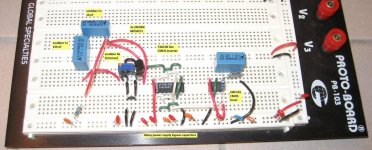
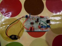
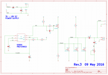
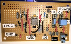
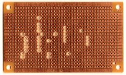
You can do this lots of different ways but the most common here on diyAudio is to put together a little bellringer test jig, either on your solderless breadboard, or on a piece of Veroboard ("Stripboard" in the US), or on a printed circuit board. Images below. Some people prefer a bellringer test jig because using it requires no calculations at all. For those who dislike exponents and scientific notation (example: 0.1 microfarad = 1.0E-7 farads), this is a delight.
Although a bellringer test jig is handy, you can get the same result with just a signal generator and your 'scope. Some people prefer this because they already own an oscilloscope and a signal generator; why build (and keep, and remember where you put away??) a test jig when you can accomplish the same objective without it? Here is a link to a post #561 that shows how. It's for self starters and independent-minded people only.
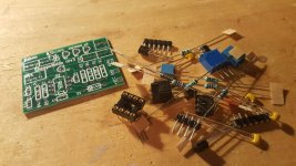
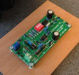
Bellringer test jigs go by the name "Quasimodo" (full featured PCB) and/or "Cheapomodo" (bare bones, inexpensive PCB) here on diyAudio. I am selling off my remaining inventory of Cheapomodo kits in the Vendors Bazaar, if for some reason you don't feel like sourcing the parts yourself. I also wrote up a detailed set of instructions on how to use bellringers; it is a .pdf attachment to post #1 of the Quasimodo thread, here.
_
In my experience, what works best in practice is to create an LC resonant circuit between the transformer leakage inductance "L", and a known capacitor "C" whose value is intelligently chosen. Measure the resonant frequency "f_resonant" and then use f_resonant and C to calculate L. Done.
You can do this lots of different ways but the most common here on diyAudio is to put together a little bellringer test jig, either on your solderless breadboard, or on a piece of Veroboard ("Stripboard" in the US), or on a printed circuit board. Images below. Some people prefer a bellringer test jig because using it requires no calculations at all. For those who dislike exponents and scientific notation (example: 0.1 microfarad = 1.0E-7 farads), this is a delight.
Although a bellringer test jig is handy, you can get the same result with just a signal generator and your 'scope. Some people prefer this because they already own an oscilloscope and a signal generator; why build (and keep, and remember where you put away??) a test jig when you can accomplish the same objective without it? Here is a link to a post #561 that shows how. It's for self starters and independent-minded people only.
Bellringer test jigs go by the name "Quasimodo" (full featured PCB) and/or "Cheapomodo" (bare bones, inexpensive PCB) here on diyAudio. I am selling off my remaining inventory of Cheapomodo kits in the Vendors Bazaar, if for some reason you don't feel like sourcing the parts yourself. I also wrote up a detailed set of instructions on how to use bellringers; it is a .pdf attachment to post #1 of the Quasimodo thread, here.
_
Attachments
Last edited:
http://www.hagtech.com/pdf/snubber.pdf
Interesting article about how calculate yours diodes bridge snubbers.
***** Have fun **

Interesting article about how calculate yours diodes bridge snubbers.
***** Have fun **
Excellent job, soundhappy! Hagerman's article is bibliography reference #1 in the Quasimodo design note. Here are the others:
References
References
- Hagerman, Jim (1995). Calculating Optimum Snubbers. Retrieved September 7, 2013 from: http://www.hagtech.com/pdf/snubber.pdf .
- Jones, Morgan (2013). Rectifier Snubbing – Background and Best Practices, Linear Audio – Volume 5, (pp. 7-26). Castricum (Netherlands): F&N Eigen Beheer. Also http://www.linearaudio.net .
- Application Dept, APD Semiconductor (2006). AN1012 – Reverse Recovery Time of the Super Barrier Rectifier. Retrieved September 7, 2013 from: http://www.diodes.com/pdfs/apd/AN-1012_TRRComparison_v0.2.pdf .
- Cornell Dubilier, Inc. (2005). Application Guide – Designing RC Snubber Networks. Retrieved September 7, 2013 from: http://www.cde.com/catalogs/igbtAPPguide.pdf .
- Basso, Christophe (2005). How to Deal with Leakage Elements in Flyback Converter:s AN1679/D. Retrieved September 7, 2013 from: http://www.onsemi.com/pub_link/Collateral/AN1679-D.PDF .
- Hewlett-Packard. (2012). Boonton Q-Meter Type 160-A, 1946. Retrieved September 7, 2013 from: HP Virtual Museum: Boonton Q-Meter Type 160-A, 1946 .
- Butler, Lloyd (1988). An Experimental “Q” Meter. Retrieved September 7, 2013 from: AN EXPERIMENTAL "Q" METER .
- AnaTek Corp (2012). Blue Ring Tester Kit Assembly & User Manual. Retrieved September 7, 2013 from: http://shop.anatekcorp.com/clientuploads/directory/products/pdfs/BLUErt%201.pdf .
Enjoyed the article . Nice bit of data generated. Question your thought on over danping vs critical that Morgan used . I do see the better safe than sorry view point. Regards
The good news is, if you use a bellringer test jig that stimulates the transformer resonant circuit 120 times per second (as a fullwave rectifier would), you can actually see the waveform shapes with your own eyes, as you adjust the potentiometer that sets the damping factor. Then simply choose the waveshape that you like best and to heck with other people's preferences and recommendations. Neither Morgan Jones, nor I, nor Jim Hagerman, nor anyone else, need ever know what you selected.
LOL do not let SY know you said that.The good news is, if you use a bellringer test jig that stimulates the transformer resonant circuit 120 times per second (as a fullwave rectifier would), you can actually see the waveform shapes with your own eyes, as you adjust the potentiometer that sets the damping factor. Then simply choose the waveshape that you like best and to heck with other people's preferences and recommendations. Neither Morgan Jones, nor I, nor Jim Hagerman, nor anyone else, need ever know what you selected.

Point taken. Landing a probe on Mars takes the right calculation , a proper target , MONEY and tracking. The question here for me is what is the proper target. 🙄I agree. We are not trying to land a probe on Mars.
😎
Using whatever decision procedure you trust the most, choose a design objective. It could beThen build prototypes and measure them. Tweak component values, adjust topologies, tinker with modifications, until you achieve the design objective. Then you are done.
Your "decision procedure" could, if you so choose, sidestep the actual decision itself; you could outsource that to another person. A professor, a guru, a Trusted Authority. Then if something goes wrong It's Not Your Fault, which is one of the reasons why external consultants are so popular.
- Find a circuit design which maximizes measurementX.
- Find a circuit design which minimizes measurementY.
- Find a circuit design which gives (measurementZ = FixedConstantK) as closely as possible.
Your "decision procedure" could, if you so choose, sidestep the actual decision itself; you could outsource that to another person. A professor, a guru, a Trusted Authority. Then if something goes wrong It's Not Your Fault, which is one of the reasons why external consultants are so popular.
Very good methodology . Letting other do the decision for you is a choose though it not decision at all on your part . Too often the American way of fixing blame and not fixing the problem is taken . Have a fine day your input is interesting after all.Using whatever decision procedure you trust the most, choose a design objective. It could beThen build prototypes and measure them. Tweak component values, adjust topologies, tinker with modifications, until you achieve the design objective. Then you are done.
- Find a circuit design which maximizes measurementX.
- Find a circuit design which minimizes measurementY.
- Find a circuit design which gives (measurementZ = FixedConstantK) as closely as possible.
Your "decision procedure" could, if you so choose, sidestep the actual decision itself; you could outsource that to another person. A professor, a guru, a Trusted Authority. Then if something goes wrong It's Not Your Fault, which is one of the reasons why external consultants are so popular.
Last edited:
I have found that once you get in the right neighborhood for R with QUASIMODO there is a range where the waveform changes so little over a surprising variety of R values that one can get really picky if you want but, in my LIMITED experience, all you have to do is get close to get rid of the ringing.
Not as if you will need 0.1% resistors!
My first tested transformer (for the mono J2 project) you can go between 20R and 38R with the slightest difference for the first peak.
I get the feeling there is no reason to obsess over the EXACT value of R but every reason to incorporate the snubber.
I am thinking it is better to go high than low on the value of R. I would worry one can go too low and likely lose some life in the sound of your amplifier. But you cannot beat QUASIMODO for telling you where the neighborhood is. You can pick the house you want once you get there.
- Status
- Not open for further replies.
- Home
- Amplifiers
- Pass Labs
- Better rectifier for the SIT 1