For my WNA MKII headphone amp I search for a better railsplitter (virtual ground)
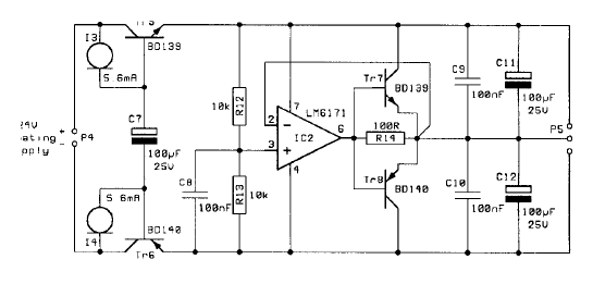
The current railsplitter looks like this (IC2: LM6171, TR7: BD139, TR8: BD140)
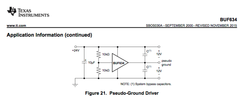
Now I found a hint in BUF634 datasheet. My question, how much could be the value of the both cups C (1) on the output?
In the current amp C (1) are 220µF + 100µF bypassed with 2x 100nF.
Offers the BUF634 really a better way, or should be a combination of an OPA + BUF634 better?
I read this hints too, but they needs an additional PCB.
http://www.diyaudio.com/forums/solid-state/234665-virtual-ground-regulated-rail-splitter.html
The complete WNA MKII schema and buildings
blue-danube DIY audio - WNA MKII Modifications

The current railsplitter looks like this (IC2: LM6171, TR7: BD139, TR8: BD140)
Now I found a hint in BUF634 datasheet. My question, how much could be the value of the both cups C (1) on the output?
In the current amp C (1) are 220µF + 100µF bypassed with 2x 100nF.
Offers the BUF634 really a better way, or should be a combination of an OPA + BUF634 better?
I read this hints too, but they needs an additional PCB.
http://www.diyaudio.com/forums/solid-state/234665-virtual-ground-regulated-rail-splitter.html
The complete WNA MKII schema and buildings
blue-danube DIY audio - WNA MKII Modifications
The LM6171 circuit has a cap on the input and output.
Why not put the bottom (normal to GND) of R1 to 1/2 +Vcc and put a large cap on the bottom (normal to GND) of R2?
This will result in a divider that does not need to handle the full output power.
Why not put the bottom (normal to GND) of R1 to 1/2 +Vcc and put a large cap on the bottom (normal to GND) of R2?
This will result in a divider that does not need to handle the full output power.
@DUG
I don't want to change this.
I think about to cancel the output cap (it's really a nonpolar BlackGate 1000µF). In this case I need the railsplitter.
I don't want to change this.
I think about to cancel the output cap (it's really a nonpolar BlackGate 1000µF). In this case I need the railsplitter.
Last edited:
Supplement: My WNA use no input cap C1 too and I don't want to change more. I think only about the railsplitter.
Could BUF634 both C (1) 220µF + 100µF bypassed with 2x 100nF drive?
Could BUF634 both C (1) 220µF + 100µF bypassed with 2x 100nF drive?
datasheet said:The BUF634 device can deliver up to ±250-mA continuous output current. Internal circuitry limits output current
to approximately ±350 mA; see Figure 10. For many applications, however, the continuous output current will be
limited by thermal effects.
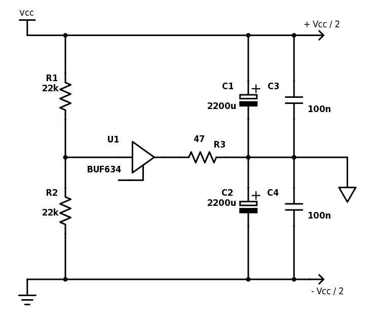
I use something like this.
Essentially, the BUF634 is used only to provide DC reference, because AC signals bypasses it via C1||C2||C3||C4.
With a setup like that, unless you have large DC currents to sink to VG, you can get away even with lower current spec-ed buffers and op-amps.
R3 needs to be sizes according to the DC current your circuit is sinking to VG (and the amount of DC offset you want to tolerate), and together with C1||C2||C3||C4 to tune the low pass filter.
any audio connected output stage really should be biased at least a bit into Class AB
and stability can be designed for - the 100 uF output C divider makes it a little diferent but https://www.maximintegrated.com/en/app-notes/index.mvp/id/5597 shows issues, an approach
if the C are big enough then yes the last post can work - again have to "do the numbers" - what headphone Z ?, how low do you really need to go?
Last edited:
any audio connected output stage really should be biased at least a bit into Class AB
and stability can be designed for - the 100 uF output C divider makes it a little diferent but https://www.maximintegrated.com/en/app-notes/index.mvp/id/5597 shows issues, an approach
if the C are big enough then yes the last post can work - again have to "do the numbers" - what headphone Z ?, how low do you really need to go?
The one I posted is an just example of what I used in one of my last projects.
That one, has a cutoff frequency of 0.76Hz.
IOW, as an example, to move a bit closer to audio frequency, a 20Hz AC signal to VG will find a 47 Ohms path to the BUF64, and a ~1.8 Ohms path via the capacitors.
It all depends on what are the constraints of your circuitry.
How much +- rail unbalance can your circuit tolerate?
How much DC current is sinking to VG?
How much idle current can you afford?
Rail unbalance is given by the VG circuitry DC output impedance (~47) in the posted schematic multiplied by the the DC current to VG.
For the trivial resistor divider, DC output impedance is R/2 (where R is the value of the split resistors).
It is possible that even the simple resistor divider is enough, w/out any need of active components, if, given your circuit DC current to VG, you can reduce R to fit your rail unbalance budget.
Note also that, with both circuits, if the idle DC current to VG is relatively constant, you can always achieve perfect balance by adding a precision trimmer to the resistor divider.
- Status
- Not open for further replies.
- Home
- Amplifiers
- Headphone Systems
- Better railsplitter (virtual ground)