Aha, a lot more output voltage and power than for a typical POL pre regulator, like the undocumented example in the datasheet, which I like to compare to Vicor´s Voltage transforming Module.
Because they use a high fsw (1.4 MHz) regulation can be very quick, but they have limited voltage and power range.
Your construction looks rather compact I´ll hope You had not to change some parts at the left side...
Much luck,
Heinz!
Because they use a high fsw (1.4 MHz) regulation can be very quick, but they have limited voltage and power range.
Your construction looks rather compact I´ll hope You had not to change some parts at the left side...
Much luck,
Heinz!
Chris,
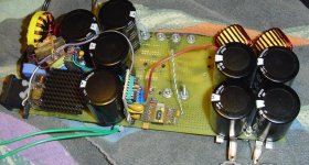
I noticed in your image that your using tantalums. I can't tell if you using them for snubbing or some other function where they might receive reverse voltage (transient spikes perhaps?). FWIW, tantalums tend to have very short lives if a reverse voltage is applied to them.
Are you using a ferrite core for the switching toriod transformer or an iron powder core? Ideally you probably want to use a ferrite.
Also be aware that using multiple smaller output caps in parallel is preferable over a small number of large caps. The smaller caps connected in parallel will have lower ESR and provide a larger surfaces area (when combined together) which enables them to disappate heat better. The hotter the temperature the shorter the life of the cap. The lower ESR also helps in noise reduction in output filtering.
That thing your looking at in the picture is not part of the main power bridge. It is a tiny standalone SMPS that converts 12V into 5 seperate isolated 12V bias'. It powers the gate drivers and the control IC. See previous post. Those five tantalums you see are the output caps for those five bias'. That toroid is in fact a ferrite core about 0.7" in diameter. I covered the bare core with mylar tape which happens to be yellow, leading you to believe it is #26 iron powder. My main power Xformer is a Magnetics toroid of P material, it's not on the board yet. I'm still testing control and gate drive. All the power devices are on the opposite side of the board and can't be seen.
- Status
- Not open for further replies.