Hi minek123,
M
Thank you,Here is simple and 'low power' (relatively speaking) Beta Nirvana with smaller fets, and 15V rails.
Sim attached. Of course bigger fets also can be still used.
View attachment 1031285
M
So we have 2 slightly different versions of the schematic. One ('original') from the post #45,
and 'new' one (proposed by Paul).
Differences between both versions (as far as I can tell):
a) simpler compensation scheme for new version
b) 'balanced' Q1 behaviour
c) Ideal OLG plot, with higher gain margin (24), and phase margin close to ideal (88).
d) same capabilities to shape fft profile.
e) pretty much the same Thd
f) pretty much thesame capabilities to handle squares and output capacitance
Both versions can be easily sharing the same PCB (already done).
I'm satisfied with both of them, but I like the newer one better.
I personally don't see the need to experiment further; don't think there is much to improve..
We squeezed as much as possible from this topology and 1 pair of outputs.
Should we settle on one version, or keep it open?
Hugh, can you analyze the new one, and give us your opinion?
All sim files attached (20V + 27V) as zip.
1st version
View attachment 1031247
2nd version
View attachment 1031248
I have had another look at some of my older simulations. One of these has a nice Tian plot albeit I had doubled the closed loop gain.Here are 2 versions (20V and 27V) final (for now) of the amp sim files.
In other posts the stability network for the amplifier has been loosely described a nested feedback which many would interpret as multiple nfb pathways.
Thinking this too complex with competing poles I got rid of all other networks bar C7.
I had retained C6 as well as C7 in the older simulations and it dawned on me that signals from the bootstrap connection are in positive phase.
With increasing frequency that would increase the a.c. impedance of R8 such that Q1 is not a common emitter stage in this regard.
Sorry if I have held up progress with your printed circuit boards. Some simulation material is attached.
Attachments
Last edited:
Sorry if I have held up progress with your printed circuit boards.
No worries, we can take all the time in the world.
My 'small' board is already in production, and with some improvisation it will
handle both versions of the schematic (unless something totally new pops up).
I wasn't planning on using the bigger board for my own build anyway (but there are provisions for
both versions on it).
2nd sim shows good square waves (I extended the sim to 30ms).
Last edited:
Michael,
Let me subjectively discuss nested fb. It is the only way, of course, because you cannot be objective about the subjective.
I found in 2007 that adding nfb to conventional Class AB SS amp I noticed a huge depth of image on good recordings.
My first attempt used a ratio of nfb to gfb of 220k:33k, 6.67:1, and the depth of image was superior to a good tube amp. You know, the full orchestra from a good speaker where you would 'place' the percussion thirty feet behind the speaker, and the soloist three feet in front. A revelation.
I tried to get rid of the nfb to simplify the circuit but with every time, and with any design, I lost this depth of image.
So, I resolved in the future it would be a feature and did manage to reduce the effect to a ratio of around 15 to 30 to 1.
When I talk about it, I have met peels of laughter, and even derision. You can't measure depth of image, but to many audiophiles it's critical and one of the reasons many only buy tube amps at high cost. The purists have denounced nfb because it increases distortion, period. No consideration of the nature of the harmonics - it's all just distortion and it has to be removed.
I'm reluctant to talk in detail with my amp designs. I suspect Papa knows about this phenomenon too, and he mentions that if you can achieve a -90 degree phase shift of the second harmonic you will have depth of image. Observe the phase shifts of the second harmonic of the opamp AN. No one argues with his designs, and few ask why he does what he does. He has been very successful, and he never opens up arguments.
So when mention that the math poles and zeroes are complicating things, I suggest that depth of image might be a casualty. Simplifying the AN to make it easier to analyse may have a down side........ and since we can't measure depth of image, you can only assess it with a working model with good speakers and a good recording. The audiophile 'dream'!
Hugh

I appreciate your open and honesty comments about a very polarized subject, distortion. Having built several of your designs, I can confidently say, “keep doin’ what your doin’ Hugh!!”
I would like to build this design also, just holding out for an elegant 2 sided layout. That part is beyond my skill set 😂
I would like to build this design also, just holding out for an elegant 2 sided layout. That part is beyond my skill set 😂
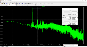
Hi Hugh, I guess you are looking at the second harmonic in the SPICE error log. Some of the phase shift that registers there is due to the low pass RC input filter. Although it may be nice for the second harmonic to be in opposite phase to the fundamental at 90 degrees - this figure varies somewhat according the output voltage. Maybe negative phase could be judged by falling inside some prescribed limits. A lot of listening involves low output power where variations would be low. One could also compare IMD profiles - I have done a 19Khz plus 20kHz with results attached.Michael,
Let me subjectively discuss nested fb. It is the only way, of course, because you cannot be objective about the subjective.
I found in 2007 that adding nfb to conventional Class AB SS amp I noticed a huge depth of image on good recordings.
My first attempt used a ratio of nfb to gfb of 220k:33k, 6.67:1, and the depth of image was superior to a good tube amp. You know, the full orchestra from a good speaker where you would 'place' the percussion thirty feet behind the speaker, and the soloist three feet in front. A revelation.
I tried to get rid of the nfb to simplify the circuit but with every time, and with any design, I lost this depth of image.
So, I resolved in the future it would be a feature and did manage to reduce the effect to a ratio of around 15 to 30 to 1.
When I talk about it, I have met peels of laughter, and even derision. You can't measure depth of image, but to many audiophiles it's critical and one of the reasons many only buy tube amps at high cost. The purists have denounced nfb because it increases distortion, period. No consideration of the nature of the harmonics - it's all just distortion and it has to be removed.
I'm reluctant to talk in detail with my amp designs. I suspect Papa knows about this phenomenon too, and he mentions that if you can achieve a -90 degree phase shift of the second harmonic you will have depth of image. Observe the phase shifts of the second harmonic of the opamp AN. No one argues with his designs, and few ask why he does what he does. He has been very successful, and he never opens up arguments.
So when mention that the math poles and zeroes are complicating things, I suggest that depth of image might be a casualty. Simplifying the AN to make it easier to analyse may have a down side........ and since we can't measure depth of image, you can only assess it with a working model with good speakers and a good recording. The audiophile 'dream'!
Hugh
I have changed the circuit I posted so it is a match with your except for the compensation schemes. When that is done the results for various measures are identical - for example both give minus-106.9 degrees for second harmonic at the same output setting.
The other factor in common is the op.amp and one could conclude with the Gain Bandwidth product this generates this is enough to iron out minor differences. minek123 is showing TL071 as an option, in post 49 he showed a photo of a square wave on his 'scope and claimed this worked as well as LT1056. My tests included a 100n capacitor in parallel with the load.
Attachments
I have been 'converted' too after experimenting with the nested feedback on the AN, and also modified a 'blameless' AB amp with support from Hugh. IMO it enables a good compromise to get tight bass (high loop gain) and smoother mids/treble with more depth, that is less fatiguing to my ears. In earlier experiments/builds, I could get one or the other, seemingly based on how much global loop gain it had.
Thank you Hugh!
/Sam
Thank you Hugh!
/Sam
Michael,
Thank you for your thoughts on the H2 phase. I had noticed it did move around depending on freq and amplitude, perhaps to be expected. Mind you, I do not discount Papa's comments, he is very careful what he says.......
I think there are quite a few tests we can do with amps to ascertain stability and high fidelity. However, I have never found that a perfect square wave (implying a very high slew rate since the artefacts are 11 times the fundamental) guarantees a good sound. I do not know why; but I found that a better test is a triangle waveform which shows clearly on a CRO if there is serious unlinearity. And a square wave test at any power on an audio amp can easily destroy the output stage, and at the least burn up the Zobel (which I think is necessary because there are some very strange speakers out there).
I admit I'm more empiricist than mathematician. I put huge emphasis on the subjectives, once the serious engineering is completed. I love to listen to mass choirs, they can tell you very much and really bring out the depth of image too.
Finally, the opamp is clearly very important. I'm not sure if a TL071 will be trounced by an OPA1656, my favourite at present, but I would bet there would be a measured difference.
Thank you for your post.
Hugh
Here is an example of bass/treble control plugged right into a feedback loop.I have been 'converted' too after experimenting with the nested feedback on the AN, and also modified a 'blameless' AB amp with support from Hugh. IMO it enables a good compromise to get tight bass (high loop gain) and smoother mids/treble with more depth, that is less fatiguing to my ears. In earlier experiments/builds, I could get one or the other, seemingly based on how much global loop gain it had.
Thank you Hugh!
/Sam
Pioneer SA 520 from 1980:
Finally, the opamp is clearly very important. I'm not sure if a TL071 will be trounced by an OPA1656, my favourite at present, but I would bet there would be a measured difference.
Thank you for your post.
Hugh
I take it you mean OPA1655 the single version in this application. As an SMD type this would need a mount to fit the DIL pins. In terms of Gain Product Bandwidth this beats a TL071 by more than a dozen times.
The TL071 info on Texas Instruments website has suggested layout - small areas and short paths to the input and supply pins and any loop paths. The TL071 can be soldered directly to the board with less to worry about re possible parasitic capacitance or inductance due to an IC socket, or deterioration of pin contacts over time.
Years ago now I had contact with the proprietor of Sakura Systems and Guido Tent working at Phillips at the time. Both were fussy about IC layouts and supply decoupling with analogue and digital ICs. SMD capacitors were used extensively in these areas and in close contact with the ICs.
I think the Gain Product Bandwidth of OPA1655 puts it somewhere in the foregoing league in terms of realising the full potential and I think the present PCB layout needs to be revised.
There are SPICE models for the latter on Texas Instruments website - if these can be used.
Last edited:
Michael,
I tried to buy a single OPA1655, couldn't find one, and right now it's difficult to get any them!!
I agree the DIP8 is far the best way to fit these opamps onto a pcb, but in a couple of years the SOIC will be the only package.
I have done a MM phono pcb for an Italian customer using this IC; I was able to fit it in my workshop and it's worked very well.
HD
Hugh, I can get you OPA1655/1656 if you want (little bit over $2 a piece). Email me if you need them.
Re op.amps I looked through Minek123 's library I can see he has a subcircuit for TL071 but his simulation matches with the LT1055/6 in the LTSpice library. The respective Gain Bandwidth Product specs are 3MHz and 6.5MHz respectively. Theoretically in an identical circuit the distortion level for TL071 would be double that for LT1055/56. In looking up TL071 I see there is now an H suffix uprated version that looks a possible rival for LT1055/56.Thank you very much, Minek..... we will talk!
Hugh
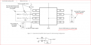
With your phono stage having a 53MHz IC , I wonder, in an asking sense, if there is a convenient point on your board where an SMD chip capacitor having low esr might fit between the supply rails to connect the two. Rail to rail op.amps should be free from phase reversal issues in Nirvanna the amplifier.
The image below relates to TL071.
Attachments
Last edited:
Michael,
Normally the datasheets suggest a 100nF cap at each rail close to the IC, but not between the rails AS WELL?
I have not seen before; does it greatly improve the performance and how does it do it?
HD
Normally the datasheets suggest a 100nF cap at each rail close to the IC, but not between the rails AS WELL?
I have not seen before; does it greatly improve the performance and how does it do it?
HD
I have used this strategy in my DIY amplifier which has been in existence for a couple of decades at least so I cannot comment from a subjective viewpoint.Michael,
Normally the datasheets suggest a 100nF cap at each rail close to the IC, but not between the rails AS WELL?
I have not seen before; does it greatly improve the performance and how does it do it?
HD
I built this on IC project board. It uses three dual op.amps for phono, and two line inputs. It has a remote volume control but no remote switching I have looked at Silicon Chip magazine articles for March and April 2019 for info on how to implement this and am attracted to the idea of having tone controls which can be switched in or out as I have kept all my vinyl.
There was an earlier version of this published in 2011 that lacked tone controls and from memory that had the usual bypass arrangements for both rail supplies. In the update there are 100uF capacitors in parallel with 100nF to ensure low impedance at a range of frequencies where those strung between the 15 Volt rails equal to 30V total need to be 35V or more.
The charge in capacitors is a function of the square of the voltage applied. There are electrons on one plate and holes on the other while the capacitor to maintain balance In that way any disturbance can be swamped out by the energy within.
I could be wrong in saying this however I think Douglas Self commented on NE5532/4 with a capacitor connecting between the supply rails.
Looking at Walt Jung's Audio IC Op-Amp Applications 1st edition he said those with Gain Bandwidth Product exceeding 10MHz need great care with supply decoupling. The minimum figure for LM833 is at that level.
Last edited:
Hi Guys,
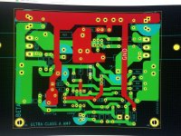
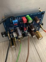
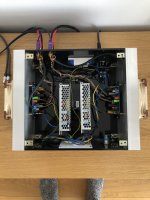
minek123 made me post here 🙂 BETA Nirvana / ALPHA OPAMP Nirvana assembled on my lame PCBs. They arrived yesterday, so as it was Friday I managed to finish the amps. PCBs designed as per schematic in post #114 by Hugh. Changes: c7 (330p), c6 (6.8p), q1 (ksa992), q3 (bd140), r19/r20 (0.18r), supply voltage 26v.
Opamps are TL071 (last 2 found in my dustbin) - offset 19.5mv and 3.5mv
If you can help me improve on KiCad layout or point what to change to make it better I’m willing to do it and share gerbers. I’m just a hobbyist as far away from electronics in my daily work life as one can be 😉
The amp is splendid. Thanks guys for the project
Cheers
Łukasz
Attachments
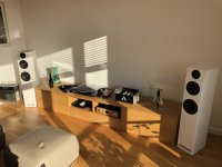
This tray sitting next to the turntable - I guess it's for a bottle of (red) wine and cheese crackers?
🙂
🙂

- Home
- Amplifiers
- Solid State
- Beta Nirvana Class A New Amp