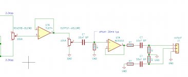
Okay here's an updated schematic.
I've added a buffer after the mixer potentiometer to make sure the output stays consistent (it was getting loaded by the Volume pot).
The volume pot is now 10k, with a 100k current leak resistor on the NE5532 input for an offset of 20mV TYP.
I've also changed all of the coupling capacitors from .47uF film to 10uF bi-polar electrolytic to preserve more extreme bass.
Attachments
Make sure you include adequate supply bypassing for the 5532 (they do tend to appreciate at least a 100n across the rails nearby).
With such a relatively powerful part, you could probably drop the 220R to 100 or even 47 ohms.
Is a 10kA a log pot? The output volume should be one at least (though I imagine the required adjustment range may well be small enough for a "fake log" to be entirely feasible - in which case you would use a 47k lin with an additional 10k resistor between wiper and ground, exploiting the generally better channel tracking of linears).
Is your maximum expected output level really just 2.2 Vpp? That would only be about 0 dBu, or just about the minimum line level typically employed on balanced connections. I would aim for roughly 10 dB more. No need to absolutely overdo it for what looks to be an instrument type circuit, and I'm not sure what your power supply situation is like, but +6..+10 dBu would definitely be nice.
Make sure you include adequate supply bypassing for the 5532 (they do tend to appreciate at least a 100n across the rails nearby).
With such a relatively powerful part, you could probably drop the 220R to 100 or even 47 ohms.
Is a 10kA a log pot? The output volume should be one at least (though I imagine the required adjustment range may well be small enough for a "fake log" to be entirely feasible - in which case you would use a 47k lin with an additional 10k resistor between wiper and ground, exploiting the generally better channel tracking of linears).
Is your maximum expected output level really just 2.2 Vpp? That would only be about 0 dBu, or just about the minimum line level typically employed on balanced connections. I would aim for roughly 10 dB more. No need to absolutely overdo it for what looks to be an instrument type circuit, and I'm not sure what your power supply situation is like, but +6..+10 dBu would definitely be nice.
I usually put .1uF caps on each rail right next to every single IC. I agree about the 220 ohm output resistors dropping to 100 ohms (as per the Jensen document).. I put 220 ohms in there because my design already uses those and I'm always hesitant to add new BOM lines. Maybe I'll just put two 220 ohms in parallel.
Yes, the volume pot is audio taper and the output level was just going to be 2.2Vpp. Power supply is +/-15V, so I should have no problem raising it.
Okay here's an updated schematic...The volume pot is now 10k, with a 100k current leak resistor on the NE5532 input for an offset of 20mV TYP. I've also changed all of the coupling capacitors from .47uF film to 10uF bi-polar electrolytic to preserve more extreme bass.
I suggest an small circuit modification. Move the 10uF coupling cap. currently located after the volume pot. to before the volume pot. This will block any D.C. from appearing across the pot. As currently drawn, if there is D.C. present across the volume pot., it will increase or decrease with the volume level setting, thereby sending a low frequency transient to the output stage whenever the volume is adjusted. Each new D.C. level will re-stabilize, but still might easily be breifly audible and yell amateur DIY. The 10uF coupling cap. is large enough in value to not audibly filter the deep bass with the 10K volume pot. resistance. The volume pot. would also function as the leak resistor.
If you do that, you have again the problem of the DC bias current flowing through the wiper, which is definitely to be avoided, as Mark said in post 14.
If you do that, you have again the problem of the DC bias current flowing through the wiper, which is definitely to be avoided, as Mark said in post 14.
Yup. Overlooked the bias current of the bipolar input stage of the NE5532. Never the less, the volume pot. is left vulnerable to input source D.C. unless it is blocked.
Yup. Overlooked the bias current of the bipolar input stage of the NE5532. Never the less, the volume pot. is left vulnerable to input source D.C. unless it is blocked.
Hi Ken, the signal that is going into the circuit is already centered at 0V. So unless the stages shown introduce a DC offset that can cause what you're talking about, I didn't see a need for the additional capacitor.
Hi Ken, the signal that is going into the circuit is already centered at 0V. So unless the stages shown introduce a DC offset that can cause what you're talking about, I didn't see a need for the additional capacitor.
Yes, as long as there is not DC presented by any upstream circuitry nor source component. Even if there were, it would still be blocked by the coupling cap. located just after the volume pot. after a brief re-settling period. This is more an concern over having an artifact free user interface.
Hi Ken, the signal that is going into the circuit is already centered at 0V. So unless the stages shown introduce a DC offset that can cause what you're talking about, I didn't see a need for the additional capacitor.
When designing a circuit (or anything else) you also need to consider failure modes.
For example...
What happens to the next stage (device) if the opamp shorts to the +supply rail?
What happens to this stage if the previous stage (device) produces a DC offset?
- Home
- Source & Line
- Analog Line Level
- Best ways to add balanced output to line-level circuit?