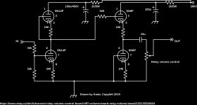
The buffers drive the volume control. The impedance varies with the position.
Starting to think replacing the 1M grid leak with two 510k and tying the midpoint to grid is the best idea.
Starting to think replacing the 1M grid leak with two 510k and tying the midpoint to grid is the best idea.
This will add noise, try a current source on the first tube's cathode instead of a resistor.
This would upset the operation of the circuit. Top and bottom parts must match.
Starting to think replacing the 1M grid leak with two 510k and tying the midpoint to grid is the best idea.
I would keep those parts as low in value as possible to preserve bandwidth.
Hopefully the source can drive 100k.
Put the volume control between the gain stage and the buffer (Floating DC).
It does not reduce the gain but it does not ruin your buffer stage.
That would upset the operation of the circuit. The input stage must be unloaded.
A current source is a very high value resistor and as long as the current matches (bias voltage same) there should be no problem. As the anode load is a cc, this can be done on the cathode side as well, looks similar to a phase splitter, without gain. As there is a buffer as well there is no issue with the load of this circuit.
place a resistor 40% the value of your volume pot between the pot and the 10uf output capacitor.
For those who are interested. My final solution was to replace the 1M on the input
with a voltage divider make from two 33k resistors. Works perfectly...
Yup.
place a resistor 40% the value of your volume pot between the pot and the 10uf output capacitor.
R of the volume control changes with position, and the "volume" relay control is after the gain... Why not just attenuate pre-gain, right?
In this case i would replace the 2 resistors with the volume control an connect the output directly with the tubes. Now the buffer amp has no use, only if the volume control is fully open you benefit from this buffer. You just add more noise and no drive on the output. This is bad design.
The volume control dips as low as 2k. The buffer drives it. I thought I mentioned that somewhere...
In this case i would replace the 2 resistors with the volume control an connect the output directly with the tubes. Now the buffer amp has no use, only if the volume control is fully open you benefit from this buffer. You just add more noise and no drive on the output. This is bad design.
The buffer is for the input stage, so that it can operate properly, unloaded.
Only in this way do the tube sections cancel their distortion as intended.
This is good design.
Sure, but it has to drive the next stage (long cables to the power amp etc), not a volume pot. The output impedance now varies with the position of this pot, thus it is a bad design.
Sure, but it has to drive the next stage (long cables to the power amp etc), not a volume pot. The output impedance now varies with the position of this pot, thus it is a bad design.
With a larger coupling cap, this design will drive 32R headphones. A varying load above 2k hardly seems like a problem. And it's not a pot, it's a relay volume control.
Last edited:
The cap is in front of the volume pot. When this pot is in mid position you will have a 1k resistor in series with your 32ohm headphones (in case it is a linear one, if it is a log one it even worse) so it can not drive anything!
It will drive 32R instead of a pot FFS... Obviously you couldn't drive a 32R load from a 1k source! The lowest load connected to this stage is 10k Regardless, it works as designed. Now with the right amount of gain. 😀
if the volume control is not a constant load, attenuating the input is the best way to go.
i am using high output on the 6922 preamp I have. 50v p-p to attain 80v p-p SS amplifier output. Sounds fantastic.
i am using high output on the 6922 preamp I have. 50v p-p to attain 80v p-p SS amplifier output. Sounds fantastic.
Last edited:
- Home
- Amplifiers
- Tubes / Valves
- Best way to reduce gain in this circuit?