Hi,
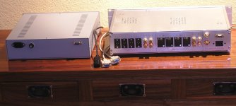
I have two enclosure as shown in the diagram below

There are 14 wires (16AWG) that will run from enclosure 1 to enclosure 2 (enclosure 1 has all the power supply).
One simple way to do this would be to drill holes in both the enclosures and run all the wires from enclosure 1 to enclosure 2. The problem i have there is that enclosure 1 is then coupled to enclosure 2. So if i wanted to work on either enclosure independently it becomes a headache, as i'll have to always keep both of the eclosures together.
Is there any solution by which the wires from enclosure 1 can be kept detachable from enclosure2? That if i want to work on either of the enclosures , i can just detach the cables like IEC inlet ?
Thanks.
I have two enclosure as shown in the diagram below
There are 14 wires (16AWG) that will run from enclosure 1 to enclosure 2 (enclosure 1 has all the power supply).
One simple way to do this would be to drill holes in both the enclosures and run all the wires from enclosure 1 to enclosure 2. The problem i have there is that enclosure 1 is then coupled to enclosure 2. So if i wanted to work on either enclosure independently it becomes a headache, as i'll have to always keep both of the eclosures together.
Is there any solution by which the wires from enclosure 1 can be kept detachable from enclosure2? That if i want to work on either of the enclosures , i can just detach the cables like IEC inlet ?
Thanks.
Perhaps a 14 pin automotive connector like this?
https://www.aliexpress.com/item/1005002416059904.html
https://www.aliexpress.com/item/1005002416059904.html

If this is stereo, it might be better to use two cables, each with half the pins.
Why, a 7 pin automotive connector of course!
A trailer plug and socket for example: https://www.amazon.co.uk/upain-Conn...19324&linkCode=df0&psc=1&tag=bingshoppinga-21
A trailer plug and socket for example: https://www.amazon.co.uk/upain-Conn...19324&linkCode=df0&psc=1&tag=bingshoppinga-21
NeoTheOne:
https://www.aliexpress.us/item/3256805705558820.html?spm=a2g0o.productlist.main.35.32d52iji2ijidt&algo_pvid=006e0849-9b91-4e79-96f4-e5652b76e97e&algo_exp_id=006e0849-9b91-4e79-96f4-e5652b76e97e-17&pdp_ext_f={"order":"40","eval":"1"}&pdp_npi=4@dis!USD!9.10!7.73!!!9.10!7.73!@!12000034730518857!sea!US!0!ABX&curPageLogUid=rlV8rPms3uYk&utparam-url=scene:search|query_from:
You'll need two sets, of course.
Regards,
Scott
6-9v ac from step down power transformers and 5v dc from LPSU. The loads will draw about .1 amps of current.What sort of signals and voltages will you be passing down the wires?
My good fellow, let me give you some valuable advice. You DO NOT want to try and construct a cable with say more than 6 wires/ connectors. The mega-connectors make it mega hard to connect all those wires! Especially the ex-military ones! Try it and see.
Instead find a standard cable or two that have what you need.
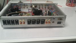
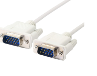
For me it was a standard 9 pin VGA type cable. Not sure what they are called. You just need to chassis mount a connector on each side and buy your cables online forever. 9 pin is good because there are 2 "easy" rows to solder to on the inside, top and bottom. Screw-locking makes the connection very tight. 20 years old and still working great.
Two 9 pin cables should do it for you. (Edit- second picture shows some options, that's not one cable, you get the idea.)
EDIT- make sure to actually test each input/output pin set on the wire in case you get one that for some reason crosses over internally. Also, for saftey, it is usually advised that PS chassis mount receptacle be female so if someone touches the chassis mount they dont short anything out...including them. But depends on your power and voltage and so on, may not be an issue.
Instead find a standard cable or two that have what you need.
For me it was a standard 9 pin VGA type cable. Not sure what they are called. You just need to chassis mount a connector on each side and buy your cables online forever. 9 pin is good because there are 2 "easy" rows to solder to on the inside, top and bottom. Screw-locking makes the connection very tight. 20 years old and still working great.
Two 9 pin cables should do it for you. (Edit- second picture shows some options, that's not one cable, you get the idea.)
EDIT- make sure to actually test each input/output pin set on the wire in case you get one that for some reason crosses over internally. Also, for saftey, it is usually advised that PS chassis mount receptacle be female so if someone touches the chassis mount they dont short anything out...including them. But depends on your power and voltage and so on, may not be an issue.
Attachments
Last edited:
My good fellow, let me give you some valuable advice. You DO NOT want to try and construct a cable with say more than 6 wires/ connectors. The mega-connectors make it mega hard to connect all those wires! Especially the ex-military ones! Try it and see.
Instead find a standard cable or two that have what you need.
For me it was a standard 9 pin VGA type cable. Not sure what they are called. You just need to chassis mount a connector on each side and buy your cables online forever. 9 pin is good because there are 2 "easy" rows to solder to on the inside, top and bottom. Screw-locking makes the connection very tight. 20 years old and still working great.
Two 9 pin cables should do it for you. (Edit- second picture shows some options, that's not one cable, you get the idea.)
I totally agree with the fact that it is better not to fabricate connection yourself, but VGA cable is made with very very skinny wires, it is not suitable for any decent voltage and amperage and distance. It is not the connector/cable type you could trust on mission critical situations overall. Also you still need to fabricate sockets and connections to them, and also source them first.
For low voltage it is better to do normal RJ45, there are tools, connectors, terminals and all the ecosystem available, cables for outside use, cable for indoor, cheap, expensive, all colors, long lengths and so on. And POE standard shows us that some voltage can be sent through it also. Not sure about Amps allowed though.
To avoid headache just not buy the cheapest and cheesiest parts available.
If those connectors are for outside and really need 16AWG, then multiple automotive trailer connectors are very good choice.
Having built many an umbilical cable, I suggest that doing so well isn't terribly difficult. Yes, it may take a little practice, but it's well worth the effort.
For example, see https://www.diyaudio.com/community/threads/build-up-umbilical-cable.379909/
Regards.
For example, see https://www.diyaudio.com/community/threads/build-up-umbilical-cable.379909/
Regards.
I kind of tried not to like this (because I was in that sort of mood), but then I see the level of workmanship. The more that I look, the more that I like. This is exactly a possibility that will serve you well. If you needed a larger gauge of wire, then simply use multiple wires in the connector, and then use two cables or something.My good fellow, let me give you some valuable advice. You DO NOT want to try and construct a cable with say more than 6 wires/ connectors. The mega-connectors make it mega hard to connect all those wires! Especially the ex-military ones! Try it and see.
Instead find a standard cable or two that have what you need.
For me it was a standard 9 pin VGA type cable. Not sure what they are called. You just need to chassis mount a connector on each side and buy your cables online forever. 9 pin is good because there are 2 "easy" rows to solder to on the inside, top and bottom. Screw-locking makes the connection very tight. 20 years old and still working great.
Two 9 pin cables should do it for you. (Edit- second picture shows some options, that's not one cable, you get the idea.)
EDIT- make sure to actually test each input/output pin set on the wire in case you get one that for some reason crosses over internally. Also, for saftey, it is usually advised that PS chassis mount receptacle be female so if someone touches the chassis mount they dont short anything out...including them. But depends on your power and voltage and so on, may not be an issue.
A trailer connector would be pretty large. Am I right? No doubt, you could use much larger ga. wire.
Last edited:
If I could do it again I would do RJ45/ ethernet. But there seemed to be somewhat of a learning curve (back then).
What about something like this?
https://www.amazon.com/Lsgoodcare-G...0b&ref_=pd_hp_d_btf_ci_mcx_mr_ca_id_hp_d&th=1
which already has cables .
https://www.amazon.com/Lsgoodcare-G...0b&ref_=pd_hp_d_btf_ci_mcx_mr_ca_id_hp_d&th=1
which already has cables .
Last edited:
That is exactly the type of connector that I would use in such a case.What about something like this?
https://www.amazon.com/Lsgoodcare-GX16-8pin-Aviation-Connector-Electrical/dp/B0BY7QGV8Q/?_encoding=UTF8&pd_rd_w=g7Vv8&content-id=amzn1.sym.a602a706-e4fe-481e-98c3-9b75060fd322:amzn1.symc.abfa8731-fff2-4177-9d31-bf48857c2263&pf_rd_p=a602a706-e4fe-481e-98c3-9b75060fd322&pf_rd_r=Y1VGWDTE1G438W3D3514&pd_rd_wg=RRTxK&pd_rd_r=1967edc6-76ea-46ab-ad66-3742da72fb0b&ref_=pd_hp_d_btf_ci_mcx_mr_ca_id_hp_d&th=1
which already has cables .
- Home
- Design & Build
- Construction Tips
- Best way to connect two enclosures