My two cents... All my tube amps have differential input that can do the conversion from SE as well, so I install both XLR and RCA connectors. XLR pin#1 goes to chassis ground and RCA is wired in parallel to pin#2 and #3. If the source is grounded then pin#3 will be grounded, if not it doesn't matter since differential input works with floating signal.

Connect the shield to pin3 and the center to pin2. Leave pin1 unconnected.
This will work on both transformer and electronic inputs. And also gives you some common mode rejection. Analog video systems (now obsolete) often did that as video signals use unbalanced 75ohm coax cable. To get better noise rejection many distribution amplifiers and other gear used a differential input stage. The BNC connector was isolated from chassis ground. The shield connection then went to the minus (-) side of a differential amplifier stage. This quasi balanced system did provide about 40db of noise rejection. Note the driving or output side of video devices always had the shield grounded.
This will work on both transformer and electronic inputs. And also gives you some common mode rejection. Analog video systems (now obsolete) often did that as video signals use unbalanced 75ohm coax cable. To get better noise rejection many distribution amplifiers and other gear used a differential input stage. The BNC connector was isolated from chassis ground. The shield connection then went to the minus (-) side of a differential amplifier stage. This quasi balanced system did provide about 40db of noise rejection. Note the driving or output side of video devices always had the shield grounded.
Last edited:
It might, but I've seen some amplifiers that use Pin 1 and 2 to wire up the XLR input to the amp. A cheap way, and one that is incompatible with the above.
The best option is the pro audio method of runing +4dBu unbalanced signal into pin 2, grounding pin 1, and providing terminating resistors at the transmitter end for pin 2 and 3. This provides impedance balanced drive for truly differential receivers, as well as a valid signal (though without the noise rejection of a balanced connection) for cheaper input circuits. Bridge balanced amplifiers without proper input circuitry will also be slightly shortchanged by this quasi-balanced approach as only one amplifier will receive a drive signal, but will still operate properly.
The best option is the pro audio method of runing +4dBu unbalanced signal into pin 2, grounding pin 1, and providing terminating resistors at the transmitter end for pin 2 and 3. This provides impedance balanced drive for truly differential receivers, as well as a valid signal (though without the noise rejection of a balanced connection) for cheaper input circuits. Bridge balanced amplifiers without proper input circuitry will also be slightly shortchanged by this quasi-balanced approach as only one amplifier will receive a drive signal, but will still operate properly.
https://funk-tonstudiotechnik.de/SYMM-MODULE.htmWhen connecting a single ended source, you often see that the single ended hot line is connected to the balanced hot line (XLR pin 2), and the ground of the singe endsed source is then connected both to the cold line of the balanced input (XLR pin 3) as well as to the ground of the balanced input (XLR pin 1).
ground at the receiver end.
I believe this last connection, to receiver ground, is not required (assuming you have enough headroom), but I'm not sure.
What do ye think?
Jan
Yes, I tend to agree, but some (well regarded) manufacturers recommend to connect pin 3 to pin 1.This is the only connection diagram that makes sense to me:View attachment 1099932
Jan
Yes. But were do you want the current to flow? Through the interconnect shield or the safety ground?If both devices have protective earth and you connect pin 1 to the unbalanced device's ground, you have a ground loop.
I wouldn't want mains hum current to flow through the unbalanced equipment, and a way to avoid that is to open the ground loop somewhere. The only safe way to do that if it is equipment that needs protective earth, is not to connect pin 1 of the balanced equipment to the ground side of the unbalanced output.
In case of equipment without protective earth, I would want a connection between the ground of the unbalanced equipment and pin 1 of the balanced equipment to get a continuous shield and to ensure I won't get large common-mode hum voltages between the two.
In case of equipment without protective earth, I would want a connection between the ground of the unbalanced equipment and pin 1 of the balanced equipment to get a continuous shield and to ensure I won't get large common-mode hum voltages between the two.
Last edited:
Pin 3 is either the inverting output in case of balanced interconnects or audio ground in case of single ended. Why would connecting audio ground or the inverting output to safety earth bring any benefit? This would either short a driven output to ground, making the op-amp driving the pin 3 output go into short circuit protection or at least become overloaded. Else, connecting audio ground to safety earth introduces possibility for a ground loop - the well known pin 1 problem.
Bill, my question is, can I leave out the left-side green connection?
https://www.diyaudio.com/community/attachments/se2bal-png.1099065/
Back when I had an active recording studio I had to do a lot of unbalanced <-> balanced interfacing. That image shows what I found to be the best way to do it. Notice that it is still a 3-wire connection, with pins 1 & 3 tied at the source (low-impedance) end, but not at the receiving end.
Last edited:
That comes from the HF teaching. All metal housings should be bonded together so no HF can get in or out. 1 & 3 open leads to an interruption. Good/bad for hum ground loops, good/bad for HF intrusion.Yes, I tend to agree, but some (well regarded) manufacturers recommend to connect pin 3 to pin 1.
Jan
Attachments
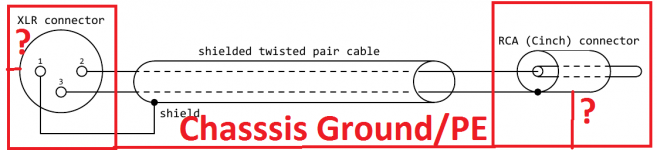
There is no single correct answer, it all depends on the actual circuitry and wiring inside the devices as well as the XLR cable itself.When connecting a single ended source, you often see that the single ended hot line is connected to the balanced hot line (XLR pin 2), and the ground of the singe endsed source is then connected both to the cold line of the balanced input (XLR pin 3) as well as to the ground of the balanced input (XLR pin 1).
ground at the receiver end.
I believe this last connection, to receiver ground, is not required (assuming you have enough headroom), but I'm not sure.
What do ye think?
Jan
The main idea is that any balancing/leakage currents (from grounds/chassis not being at the same voltage potential) shall only flow on the shield and not be part of the signal transmission wires. Which means that
- RCA center pin goes to inner conductor #1 of the XLR cable.
- RCA shell goes to inner conductor #2 of the XLR cable.
Finally, the shield of the XLR cable also goes to the RCA shell in order to carry only the balancing/leakage currents. If you don't connect the shield, you might end up taxing the common mode input range and the CMRR of the receiver unneccesarily (which ususally isn't that great with impedance mismatch, see below) and the shielding is reduced to an electrostatic shield only and a bad one as RF might easily sneak in (broken Faraday cage).
At a closer look, to improve CMRR we also want balanced impedance on the source side of the inner conductor pair which means a resistor (or R+C or whatever) equal to the output impedance must be placed in shell tap at the cable entry for inner conductor #2. Further, the inner wire pair must be twisted and the shield must be true circumferential (braided shield), not a foil shield plus drain wire. By this the screen-current induced noise (SCIN) is minimized by making it the same on both inner conductors.
The gotcha is that the balancing current on the shield is not limited (notably when both devcies are earth-grounded) and that might cause I*R voltage drop errors at the sending end's inner circuitry if the layout did not take care about these GND currents. The same can happen with improperly designed balanced inputs, though typically less severe impact. In that case, it might be better to use hybrid shell connection for the shield, with an R//C (or just a C)... which must be circumferential design, ideally, in order to reduce balancing current at mains frequencies but have the Faraday cage fully working at higher and RF frequencies. Ferrites (=CM chokes) on the cable (use them generously) help quite a bit to reduce shield currents at higher frequencies, btw.
If possible, the best additional tweak is is to bond the two device chassis together as good as possible with a low resistance and low inductance path, preferably a copper ground plane or ground grid. That reduces shield currents on the cable to insignificance (best combined with ferrites). Remember to keep loop area between the cable and the plane/grid as small as possible, to prevent magnetic field pickup.
Last edited:
My RCA-XLR cables have RCA centre to XLR pin 2 and RCA outside to XLR pin 3, each on its side of the pair. XLR pin 1 is connected to chassis and also cable shield, which is connected at the unbalanced end to RCA outside via a 10 nF NPO capacitor. So far it seems to work okay, no ground loops or RF interference reported yet. Possible RF injection to the input via the capacitor is handled by a 160 kHz lowpass filter at each input before the signal gets anywhere near silicon.
Ideally the far end would be XLR, but wishes-horses-etc.
Ideally the far end would be XLR, but wishes-horses-etc.
... or use a resistor and a capacitor in series at unbalanced end to connect the ground to the shield, or maybe connect the output as impedance balanced at the unbalanced end. With the ungrounded/floating (source) devices, where the PSU uses only a 2-terminal plug for an example, you can connect the the ground to the shield directly at the unbalanced end (although you should consider also devices which connects to this devices inputs in signal chain).My RCA-XLR cables have RCA centre to XLR pin 2 and RCA outside to XLR pin 3, each on its side of the pair. XLR pin 1 is connected to chassis and also cable shield, which is connected at the unbalanced end to RCA outside via a 10 nF NPO capacitor. So far it seems to work okay, no ground loops or RF interference reported yet. Possible RF injection to the input via the capacitor is handled by a 160 kHz lowpass filter at each input before the signal gets anywhere near silicon.
Ideally the far end would be XLR, but wishes-horses-etc.
Sorry for being so late to the party. This is a subject that has been near and dear to my heart for over 30 years as all of my projects during that time have had, as a minimum, balanced differential inputs. I have read every paper and article on the subject that I could find. I have probably forgotten half of what I learned but I would still like to add my 2 cents (maybe there is only 1 cent left 🙂).I believe this last connection, to receiver ground, is not required (assuming you have enough headroom), but I'm not sure.
What do ye think?
Jan
First, let me say that there have been a lot of excellent replies in this thread and I will not credit them all here. I would, however, like to point out KSTR's Post (#33) which addresses almost everything I can think of, and very well.
Jan, to answer your specific question, if you have adequate CMR and CM range in the receiver, you are correct that the connection to the shield on both ends should not be required from a hum and buzz standpoint. However, it is very unlikely that you do unless the chassis are very well bonded or you are using a transformer on the receiver input. Power safety ground, at least in the US, is not adequate. It is noisy and not as low an impedance as you might expect. Also, in the US, most source components are only 2-wire. As KSTR points out, it is best to use a twisted, shielded pair with heavy braid for the shield (not just foil and drain wire) to minimize the potential between the source and receiver chassis. This also completes the Faraday cage around the wiring for RF rejection. Rane's Figures 17 and 18 have always surprised me.
The "cheap and dirty" interface cable referenced in Post #2 is better than nothing and actually works pretty well if the source has a very low output impedance and the receiver has a very high input impedance. You can do much better without much effort.
I make custom interface cables with an XLR connector on the receiver side connected as per AES recommendations (cable braid is connected to pin 1). [Receiver XLR connector pin 1 is bonded to the chassis.] On the source end, I connect the cable braid to the phono plug shell. The pin 2 wire is connected to the phono plug center pin. The pin 3 wire is connected through a resistor to the phono plug shell to create a balanced source (at the source). The value of this resistor (placed within the cable phono connector) is determined by measuring the output resistance of the source at the frequency of most interest (second or third power line harmonic?) and matching it. This maximizes CMR and minimizes the CM noise to be rejected.
The connection that I just described does, in theory, create a ground loop with stereo connections due to the multiple ground connections. But that is what balanced inputs are for! If this is a concern, one channel in the receiver can terminate pin 1 to chassis through a "hum bucking resistor" with an RF bypass capacitor in parallel, just like what is often done for unbalanced-to-unbalanced connections.
Bruce, thanks for chimning in. I can agree to pretty much all you said.
One concern I have with using a cable screen to interconnect two units is the chance of a ground current running through the screen.
If the pair inside is tightly twisted and has identical impedances and capacitances to the screen it wouldn't matter, but you can't rely on that.
It would be better to run a separate cable between two chassis to equalize their stray voltages.
Jan
Jan,It would be better to run a separate cable between two chassis to equalize their stray voltages.
Jan
Your concern is valid but I personally have not had much luck with floating shields. AES strongly recommends grounding pin 1 on both ends as do most papers on the "pin 1 problem." Many approaches may work, it depends on the system. I think AES wants to maximize the probability of success with any system.
You can always try one approach and see how it works for you. It should be easy to change unless your are limited by an existing PCB layout.
Bruce
There's an interesting Linear Audio article by Hans Polak titled 'One End Only' ;-)Jan,
Your concern is valid but I personally have not had much luck with floating shields. AES strongly recommends grounding pin 1 on both ends as do most papers on the "pin 1 problem." Many approaches may work, it depends on the system. I think AES wants to maximize the probability of success with any system.
You can always try one approach and see how it works for you. It should be easy to change unless your are limited by an existing PCB layout.
Bruce
I'll send it to you.
Jan
- Home
- Source & Line
- Analog Line Level
- Best way to connect single ended out to balanced in