I learned from abraxalito a pair of near complimentary mosfets the ssm3k339/j327. These are 40v but very high gm. They follow square law to 10ma, at 100ma they are 1S and over.
I'm looking at KSA1381 and KSC3503 for VAS, high voltage cascoding, and predrivers. Not sure that's the best choice, but I think it must be close to the best.
How suitable would you say C2705/A1145 & C2229/A949 are for VAS? (Or as KSA1381/KSC3503 substitutes when the dissipated power is low?) I have about a dozen genuine Toshiba C2229/A949 on boards for recycling.
How suitable would you say C2705/A1145 & C2229/A949 are for VAS? (Or as KSA1381/KSC3503 substitutes when the dissipated power is low?) I have about a dozen genuine Toshiba C2229/A949 on boards for recycling.
I've no experience with those transistors. I'm more theoretical than hands on, these days. It seems like once you know your rated voltage, current, power, and required beta, there aren't that many options at the high voltages.
The beauty of the KSA1381/KSC3503 is they're power dissipation while maintaining some key small signal qualities.

KSC3503/KSA1381 are very good devices, if you can avoid the hfe difference. I I use them for cascode, of predriver in triple output.
KSC3503/KSA1381 are very good devices, if you can avoid the hfe difference. I I use them for cascode, of predriver in triple output.
A little while back, I received free samples of low cob equivalents made by KEC such as KTA1381Y (hFE 148-180) and KTC3503Y (hFE 115-118).
Yes, they've naturally eat a tons of their competitors.KSC3503/KSA1381 are very good devices, if you can avoid the hfe difference. I I use them for cascode, of predriver in triple output.
Bonsoir Alain,Jacques, did you obtained the smples from KEC?
Yes. On the KEC web site (KEC) type KTA1381 in the search box.
You get to a page with a black button "Request sample".
In 2016, I got them for free but had to pay for shipping with my Fedex account.
Nowadays, there could be a retailer in EU; you might check with them.
I remember people at KEC being kind and helpful.
I used the KTA/KTC for prototyping a VSSA.
Cheers,
Jacques
My "stock" comes from Mouser. Onsemi (Fairchild) manufactured. KSC3503s have hfe arounnd 93-95, the KSA1381s have hfe around 115-118.
Bonsoir Alain,
Yes. On the KEC web site (KEC) type KTA1381 in the search box.
You get to a page with a black button "Request sample".
In 2016, I got them for free but had to pay for shipping with my Fedex account.
Nowadays, there could be a retailer in EU; you might check with them.
I remember people at KEC being kind and helpful.
I used the KTA/KTC for prototyping a VSSA.
Cheers,
Jacques
KEC can be bought from LCSC direct.
I have a few of their other to126 and to220 bjts.
Most of the Onsemi devices are DSTU and ESTU versions, different gain grouping for NPN and PNP, and mine follow the same trend (above)
Hi Folks,
This seems like the best thread to ask this. I am rebuilding driver boards from a Sherwood HP-2000. It has mid-70s transistors that I can't even locate datasheets to match. I only know the current outputs recommended by an experienced fellow here, but what would you all recommend for the two stages after the RCA3100 input op amp and for the drivers? Notice that the outputs are MJ21193 and MJ21194.
Thanks so much.
Attachments
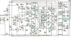

The parts listed in post #36 have you covered; 2N5401/5551 and MJE15032/33. But I don't see any voltages on the schematic so I am assuming they are nothing these parts can't handle. But a couple things:
1. The drivers have 1200 and 220pF caps on them so using fast drivers is a bit pointless. An older 4mhz part probably works fine.
2. This seems to be class AB all the way back to the op-amp, which makes me worried about thermal tracking. I would be tempted use larger VAS transistors and run the VAS class-A with a vbe multiplier where the bias adjustment is. And looking at burnt R618, the bias pot is probably also toast.
But this is an op-amp IPS, which are very hard to stabilize, so I might just but replace the entire driver board with a discrete circuit.
Or, find a faster op-amp for the IPS. And socketed chips are trouble, so I would ditch the sockets and solder them directly in place. If this is yours, I would simulate the circuit in spice and tweak it for a very conservative phase margin etc. The VI protection can also be problematic so maybe redo it for just current limiting. I expect this amp was instable both thermally and electrically.
Thanks for this info! I am digesting.
The voltage supply rails are +60 / -60...
I have an LME49710 in one of the boards, but have not located the CA3100 datasheet to compare.
The voltage supply rails are +60 / -60...
I have an LME49710 in one of the boards, but have not located the CA3100 datasheet to compare.
The ”1200 pf and 220 pf caps on the drivers” is deceiving. What you REALLY have is a lag compensated VAS stage with 1420 pF to AC ground. It would probably work BETTER if those caps were returned to a better AC ground than the power supply (which may not have adequate decoupling - too much inductance). Faster drivers are always better than slow ones - the intrinsic impedance looking into the emitter is more ideal - less chance it will go inductive at high frequency causing local instability. Personally I prefer to properly Miller compensate the VAS and ditch the “collector-base” caps on the drivers.The parts listed in post #36 have you covered; 2N5401/5551 and MJE15032/33. But I don't see any voltages on the schematic so I am assuming they are nothing these parts can't handle. But a couple things:
1. The drivers have 1200 and 220pF caps on them so using fast drivers is a bit pointless. An older 4mhz part probably works fine.
2. This seems to be class AB all the way back to the op-amp, which makes me worried about thermal tracking. I would be tempted use larger VAS transistors and run the VAS class-A with a vbe multiplier where the bias adjustment is. And looking at burnt R618, the bias pot is probably also toast.
But this is an op-amp IPS, which are very hard to stabilize, so I might just but replace the entire driver board with a discrete circuit.
Or, find a faster op-amp for the IPS. And socketed chips are trouble, so I would ditch the sockets and solder them directly in place. If this is yours, I would simulate the circuit in spice and tweak it for a very conservative phase margin etc. The VI protection can also be problematic so maybe redo it for just current limiting. I expect this amp was instable both thermally and electrically.
Op amp input stages are harder to stabilize, but not impossible. You do have to think the entire compensation scheme through. If you monkey with any of it (including those collectior base caps on the drivers) it all needs to be re-done. It can be worth it - with todays better vas and driver trannies and op amps you can build better than it was. Look at some of the Marantz input stages. When I build one, I run the stages in between the op amp and the darlingtons in class A - with 20 mA n the VAS for an EF2 output and 10 mA for an EF3. Requires heat sinks on the VAS, but that’s the price for performance.
If using MJ15024 or 21194 (equivalent at these voltages) I’d re-do the protection circuit. As is it activates way too soon. It could be simplified and made more stable.
Man, I wish I had the schooling or experience to redesign that protection circuit, or be able to remove it. It seems to compensate for a lesser than ideal design. MJ15024/25 are exactly the spare outputs I currently have, and if it goes well, I will order the MJ21193/94 from Mouser, Almost $9 each--Ouch! Under $4 just a few years ago.If using MJ15024 or 21194 (equivalent at these voltages) I’d re-do the protection circuit. As is it activates way too soon. It could be simplified and made more stable.
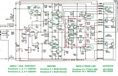
OK, here is the transistor recipe I've gathered from you all's suggestions (attached)
Attachments
- Home
- Amplifiers
- Solid State
- Best Transistors at Each Amp Stage