Steve Eddy said:
How is the back EMF of a loudspeaker fundamentally any different than the back EMF of a RLC resonant circuit?
se
well, for starters, the emf talk of a loudspeaker foundamentally helps, no, it determines, marketing of an otherwise average amp.
Can your otherwise identical rlc circuit do that? don't think so.
🙂
pinkmouse said:All true...
Brain melting after 12 hour shift at work...
Ugh. And on Saturday no less. Sounds like it's time to throw down a pint or two and get some 😴
se
It gets worse, I have done 12 hours today and yesterday, but still have Sunday and Monday to go...
... still, only half an hour to go, then I think I'll go for that beer! 😉
... still, only half an hour to go, then I think I'll go for that beer! 😉
pinkmouse said:It gets worse, I have done 12 hours today and yesterday, but still have Sunday and Monday to go...
Damn. I thought they abolished the workhouses over there? 🙂
... still, only half an hour to go, then I think I'll go for that beer! 😉
Hehehe. Well have one on me. Just tell the barman to put it on my tab. 😀
se
JFETS necessary for hi-detail and low noise?
Is a JFET input stage necessary for obtaining high detail and low noise at low power? Are JFETS lower in noise than bipolars? Amps like the JC2 describe JFET input stages, often in cascode configurations, and still use bipolar outputs.
Is a JFET input stage necessary for obtaining high detail and low noise at low power? Are JFETS lower in noise than bipolars? Amps like the JC2 describe JFET input stages, often in cascode configurations, and still use bipolar outputs.
Attachments
Hi sreten,
Good points.
However a CCS for the input pair would not be better, only more complicated. I have these transistors running at 10mA each with no emitter resistors. The impedance at their junction is very low.
Yes those grounds should go together, at the same star earth point all the others are connected to in order to minimise hum and the risk of earth loop induced distortion.
Hi traderbam,
I know what you see, but the BD139 really is integral with the output devices.
Actually some makes of BD139 are better than others. The Toshiba 2SC3421 is another good candidate for this position, especially the Y gain selected version. Geoff Moss mentions this one on his class-A site, and its the only other one I can find that is both suitable and available. These are only 75p each here in the UK.
Hi Steve Eddy,
I showed above how a 200Hz cycle loudspeaker current can double after the first cycle, pure class-A amps can't cope with that.
Some mid driver effects can arise within a 100uS time frame which is just right for interfering with tweeter drive if the amplifier's output stage is propagation delay prevented from instantaneously generating a counter current and thereby holding the output potential at the correct potential wrt input.
The problem is that no amplifier can react instantaneously, especially class-B types, and thus error voltages do develop. Unfortunately some amplifiers are very poor, especially those where the NFB node is separated from the output terminal by say a 5uH choke - the attempted correction is out of phase with the error because the error voltage on the loudspeaker side leads the current which flows though into the NFB controlled output node !
____________________________________________________
No other ideas yet ?
A class-AB Mofet amp should be much more efficiently capable of directly driving this resistive element.
Graham Maynard said:Yes those grounds should go together, at the same star earth point all the others are connected to in order to minimise hum and the risk of earth loop induced distortion.
Have to disagree, the feedback would be better connected to
the input earth return to the star point than the decoupling
return, or on your diagram you should show it as another earth
point, implying a seperate star point return, in that context
the output zobel and load return should be the same earth ?
🙂 sreten.
Graham Maynard said:I showed above how a 200Hz cycle loudspeaker current can double after the first cycle, pure class-A amps can't cope with that.
Actually you didn't show anything. You said you were attaching some scope photos but there was no attachment on that post.
The problem is that no amplifier can react instantaneously, especially class-B types, and thus error voltages do develop.
But then nothing acts instantaneously either.
Anyway, without seeing the scope photos you mentioned, there's not much to comment on.
se
Hi sreten,
I do not have any different symbol on my simulator to use for a common earth.
You are still trying to pick holes. Do you not realise that I have been building these JLH based class-A amps since they were first published in 1969, and that this is because they do not embody the flaws that have to be 'designed' out of other topologies ?
I have told you .... all of those earth points go thogether ... to the same point.
There are no runs or separate lengths of wire !
I use a minimum of symbols to illustrate circuits, and use them wherever it is visually convenient. However I separately state in my writing - star earth connectivity.
They all go together on my real-world amps, either by wires into a wider pcb track in an order which I understand, or to a star earth made up from lots of solder tags bolted tightly together in a spiral and quite literally - star pattern.
Some desiners use signal earths and dirty earths, maybe you are thinking about that. I have always used a star earth and NEVER had any decoupling or ground problems.
Continuing with your pedantic theme, if there was one milliohm of resistance in series with that earth point (the inductance would be in pico-henries ); the nfb potential across that 'wire' would be 1 /1000 / (100000+560+560) of peak output voltage, and ripple rejection further reduced by the 470 ohms in series with the very low differential node impedance, which I will not waste my time measuring because the breakthrough is already impossibly small.
Looking the other way, the psu line ripple at that point would be 1/ 1000 /100 but gain amplified by twenty = 0.0002 of rail ripple at the loudspeaker. If the rail ripple was a very poor (for the low voltage circuit suggested) 1Vp, that would be 200uVp of ripple at the loudspeaker which would be audible on directly connected headphones. I would estimate a working circuit ripple of 100mVp, so even if my instructions are ignored with regard to star wiring, you still won't hear 20uVp at the loudspeaker !
That loudspeaker current trace was Post#19 at 10:06AM.
Strange, that it has disappeared ?
It is reattached here.
Cheers .......... Graham.
Attachments
Graham Maynard said:That loudspeaker current trace was Post#19 at 10:06AM.
Strange, that it has disappeared ?
that's looks nice. Was this taken at start-up? (it does start at 0ms). if so your amp has a great start-up behavior, 🙂
can you provide some legends on the chart so we know what trace is what signal? what model of scope is it and what speaker is it? I suppose the pickup point is the speaker terminal?
some general information about how it was done would be greatly helpful in a serious discussion. but I am sure it was simply an oversight that a person as detailed and thorough as you are had it omitted.
Graham,
Thank you for the very nice circuit in post #50.
Simulations on this circuit look very good.
I have a few questions though:
are a single stage?
Along the same lines as saying an output stage using
darlingtons or sziklai pairs is a single gain stage?
Could you explain the use of the resistors 220 and 22k
on the base of the BD139?
Together with the 1n4148 and the 220 on the current
mirror they seem to help balancing the currents in the
differential pair.
Regards
Thank you for the very nice circuit in post #50.
Simulations on this circuit look very good.
I have a few questions though:
Do you mean to say that the BD139 with the outputsI know what you see, but the BD139 really is integral
with the output devices
are a single stage?
Along the same lines as saying an output stage using
darlingtons or sziklai pairs is a single gain stage?
Could you explain the use of the resistors 220 and 22k
on the base of the BD139?
Together with the 1n4148 and the 220 on the current
mirror they seem to help balancing the currents in the
differential pair.
Regards
Graham,
I believe the number of junctions is more influencial on the stability of the system than the notional number of stages. You implied earlier that you circuit had two stages and was therefore inherently stable. I inferred that you meant that each stage could only contribute up to 90 deg of phase lag and so two stages never quite becomes completely unstable. However, I disagree with this reasoning as each "stage" is not limited to 90 deg. Each junction can contribute 90 deg or more phase lag and so having three or more cannot strictly be said to be "inherently stable". It might be more stable than a 4 junction circuit, however.
I believe the number of junctions is more influencial on the stability of the system than the notional number of stages. You implied earlier that you circuit had two stages and was therefore inherently stable. I inferred that you meant that each stage could only contribute up to 90 deg of phase lag and so two stages never quite becomes completely unstable. However, I disagree with this reasoning as each "stage" is not limited to 90 deg. Each junction can contribute 90 deg or more phase lag and so having three or more cannot strictly be said to be "inherently stable". It might be more stable than a 4 junction circuit, however.
Graham Maynard said:That loudspeaker current trace was Post#19 at 10:06AM.
Strange, that it has disappeared ?
It is reattached here.
It was post #18 on my list.
Thanks for reposting it.
Anyway, you said:
I showed above how a 200Hz cycle loudspeaker current can double after the first cycle, pure class-A amps can't cope with that.
How does your plot show that pure class-A amps can't cope with an increase in current after the first cycle?
Also, I'm still wondering how the back EMF of a loudspeaker is fundamentally any different than the back EMF of an RLC resonant circuit as well as still wondering about these "reflections" you mentioned.
Basically, everything I asked in post #54
http://www.diyaudio.com/forums/showthread.php?postid=368846#post368846
se
Guys,
There is something strange about the way the posts have been retained here. Some posts and the information therein have been removed after they had been viewed.
My browser shows the missing image first appeared as post#23 ??? (I got the time wrong though.)
____________________________________________________
Hi Millwood,
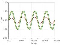
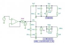
The plots were simulated for the Ariel loudspeaker.
V at terminal. V at bass driver. Current into loudspeaker terminal.
I pointed out that a pure class-A amplifier that was designed to match a nominal (5.3 ohm for Ariel) impedance, will be unable to provide the current the loudspeaker needs to maintain level output beyond the first cycle. It goes to about 370mA for 1V input which is effectively 2.7 ohms.
____________________________________________________
Hi rtirion,
The BD139 is integral with the outputs. It drives both simultaneously and will not work the same if either is removed. It is not a VAS stage, but a current splitter for the ouputs.
The output devices are the controlling factor - as long as the splitter is much faster.
I am unable to compare it with any other type of stage, and if anyone can, I'm all ears.
Yes the single diode matches the mirror voltages. The BD139 220 ohm reduces base impedance but it is self bootstrapping. 220 ohm at mirror balances differential loading. The 22k is local feedback for that stage.
The input stage characteristic is like a single PNP; the output stage characteristic is like a single NPN; thus there is a small amount of entirely natural distortion cancellation between the stages.
____________________________________________________
Hi traderbam,
4 junctios ?
There are only two that have any effect
1 the input transistor which is supported by a much faster mirror plus much faster NFB emitter follower
2 the output devices which are supported by a much faster driver.
The gain goes through the floor before any other than 1 or 2 can have an effect upon phase. Also no device can saturate so stability cannot be upset by input or (sensible) loading.
____________________________________________________
Hi Steve,
With my writing and the responses of SY and pinkmouse I thought your questions had been answered. But I'll start afresh.
The back emf of a speaker has dynamic electro-mechanical reactivity that can deleteriously combine with its electrical reactivity. Current through the output terminal has to be countered by the amplifier or loudspeaker resonances will not be damped.
Current flows out of the loudspeaker wrt the amplifier - the output terminal voltage shifts - the NFB loop corrects the error.
An amplifier always has a propagation delay due to compensation/stabilisation capacitors ( the circuit I suggested does not have or need any) or Mosfet gate capacitance in series with a resistor.
The output terminal potential shifts before the output stage can correct the error (my circuit does too, but it is faster than most). Error from crossover circuitry and mid-bass drivers can thus generate a small potential at the amplifier's output terminal, which will then directly drive the tweeter, and slightly alter the reproduced sound.
The action of compensation/stabilisation capacitors or Mosfet gate capacitance within the NFB loop is inverted so that the amplifier behaves like an inductor (hence the delay).
If the load is purely resistive there is no effect to monitor. This is why steady sinewave testing with a resistor load is useless for indicating how realistically an amplifier will drive real world loudspeakers.
Cheers ........... Graham.
There is something strange about the way the posts have been retained here. Some posts and the information therein have been removed after they had been viewed.
My browser shows the missing image first appeared as post#23 ??? (I got the time wrong though.)
____________________________________________________
Hi Millwood,
The plots were simulated for the Ariel loudspeaker.
V at terminal. V at bass driver. Current into loudspeaker terminal.
I pointed out that a pure class-A amplifier that was designed to match a nominal (5.3 ohm for Ariel) impedance, will be unable to provide the current the loudspeaker needs to maintain level output beyond the first cycle. It goes to about 370mA for 1V input which is effectively 2.7 ohms.
____________________________________________________
Hi rtirion,
The BD139 is integral with the outputs. It drives both simultaneously and will not work the same if either is removed. It is not a VAS stage, but a current splitter for the ouputs.
The output devices are the controlling factor - as long as the splitter is much faster.
I am unable to compare it with any other type of stage, and if anyone can, I'm all ears.
Yes the single diode matches the mirror voltages. The BD139 220 ohm reduces base impedance but it is self bootstrapping. 220 ohm at mirror balances differential loading. The 22k is local feedback for that stage.
The input stage characteristic is like a single PNP; the output stage characteristic is like a single NPN; thus there is a small amount of entirely natural distortion cancellation between the stages.
____________________________________________________
Hi traderbam,
4 junctios ?
There are only two that have any effect
1 the input transistor which is supported by a much faster mirror plus much faster NFB emitter follower
2 the output devices which are supported by a much faster driver.
The gain goes through the floor before any other than 1 or 2 can have an effect upon phase. Also no device can saturate so stability cannot be upset by input or (sensible) loading.
____________________________________________________
Hi Steve,
With my writing and the responses of SY and pinkmouse I thought your questions had been answered. But I'll start afresh.
The back emf of a speaker has dynamic electro-mechanical reactivity that can deleteriously combine with its electrical reactivity. Current through the output terminal has to be countered by the amplifier or loudspeaker resonances will not be damped.
Current flows out of the loudspeaker wrt the amplifier - the output terminal voltage shifts - the NFB loop corrects the error.
An amplifier always has a propagation delay due to compensation/stabilisation capacitors ( the circuit I suggested does not have or need any) or Mosfet gate capacitance in series with a resistor.
The output terminal potential shifts before the output stage can correct the error (my circuit does too, but it is faster than most). Error from crossover circuitry and mid-bass drivers can thus generate a small potential at the amplifier's output terminal, which will then directly drive the tweeter, and slightly alter the reproduced sound.
The action of compensation/stabilisation capacitors or Mosfet gate capacitance within the NFB loop is inverted so that the amplifier behaves like an inductor (hence the delay).
If the load is purely resistive there is no effect to monitor. This is why steady sinewave testing with a resistor load is useless for indicating how realistically an amplifier will drive real world loudspeakers.
Cheers ........... Graham.
Graham Maynard said:The plots were simulated for the Ariel loudspeaker.
maybe you can post the schematic / submodel used in your simulation for this Ariel speaker.
Do people really call simulated waveforms "traces"?
Graham Maynard said:V at terminal. V at bass driver. Current into loudspeaker terminal.
what if you plot the input signal on the same chart? that way it is easier to convinece you that your concerns are unfounded.
Graham Maynard said:The plots were simulated for the Ariel loudspeaker.
Simulated? You gave the impression that they were actual plots of an actual amplifier driving an actual loudspeaker.
How did you simulate the load of the Ariel?
V at terminal. V at bass driver. Current into loudspeaker terminal.
V at bass driver? Before you said that the second trace was the output of the bass driver, which would imply its acoustical output.
I pointed out that a pure class-A amplifier that was designed to match a nominal (5.3 ohm for Ariel) impedance, will be unable to provide the current the loudspeaker needs to maintain level output beyond the first cycle. It goes to about 370mA for 1V input which is effectively 2.7 ohms.
Again, how did you simulate the load of the Ariel loudspeaker? Did you just use a 5.3 ohm resistor in your simulation?
Was the amplifier simulated as well?
With my writing and the responses of SY and pinkmouse I thought your questions had been answered. But I'll start afresh.
The back emf of a speaker has dynamic electro-mechanical reactivity that can deleteriously combine with its electrical reactivity.
Huh? Its electromechanical reactivity includes electrical reactivity. What are you talking about?
Current through the output terminal has to be countered by the amplifier or loudspeaker resonances will not be damped.
Huh? Current through the output terminal has to be countered? If it's countered, you wouldn't have any current flowing. How does a loudspeaker work without any current flowing through it?
Current flows out of the loudspeaker wrt the amplifier - the output terminal voltage shifts - the NFB loop corrects the error.
Huh? Current flows out of the loudspeaker? When does this happen? There should always be as much current flowing out of the loudspeaker as into it.
An amplifier always has a propagation delay due to compensation/stabilisation capacitors ( the circuit I suggested does not have or need any) or Mosfet gate capacitance in series with a resistor.
Sure.
The output terminal potential shifts before the output stage can correct the error (my circuit does too, but it is faster than most).
What error are you speaking of?
Error from crossover circuitry and mid-bass drivers can thus generate a small potential at the amplifier's output terminal, which will then directly drive the tweeter, and slightly alter the reproduced sound.
What error from crossover circuitry and mid-bass drivers are you speaking of?
The action of compensation/stabilisation capacitors or Mosfet gate capacitance within the NFB loop is inverted so that the amplifier behaves like an inductor (hence the delay).
Mmmm. Ok.
If the load is purely resistive there is no effect to monitor.
How do you figure? The delay through the amplifier is there even if the load is resistive, yes?
This is why steady sinewave testing with a resistor load is useless for indicating how realistically an amplifier will drive real world loudspeakers.
So what has that to do with your plots? And what has it to do with pure class-A amplifiers?
se
Graham,
Your numbering may be wrong because some of the more off topic and/or personal posts in this thread were moved to Texas in a moderator clean-up.
Your numbering may be wrong because some of the more off topic and/or personal posts in this thread were moved to Texas in a moderator clean-up.
Hi Millwood,
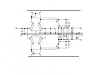
The obvious *colour* traced simulation was from the circuit is attached.
My, wouldn't a colour trace scope have been useful - not joking either.
Trace - track left by anything, draw exactly.
Digging this circuit out of the simulator via PSP with this string of windows on the tasbar made my computer crash.
Personally, I'm beginning to feel the same myself due to those who make silly comments and ask questions without first thinking for themselves about the information I am taking the trouble to communicate.
I've put the Ariel up on diyaudio before, but here it is again.
There must be an awful lot of good information lying about in dead diyaudio threads.
Hi Steve,
Now that the circuit is up, your questions should be answered. I said amplifier output - which is - V at terminal !
Steve. Your use of the word 'Huh ?' shows not only that you don't understand what I have written, but that you have an attitude which is keeping you from thinking for yourself before you ask questions.
It is not possible for me to create your understanding, but do note that I have always answered a simply presented question. Unfortunately your questions in post#76 show that the gaps are bigger than I could fill here.
Imagine what happens from one nano-second to the next, and stop using maths which will integrate a whole without revealing the differential detail therein.
Hi Linesource.
Rtirion has pointed out that the simulation of my circuit appears very good. I should like it to be known as GM25-1. ( One ohm )
I'm sure he'll confirm that the 'First Watt' audio performance is of reference standard.
It is based upon my real-world 8 ohm version. GM25-8 which has only one output pair.
Can I suggest that this really is a simple circuit to build for your tweeter to see if your ideas work. If your experiments are successful and if any other circuit arises you could then see if it matches up in real life, as opposed to on a simulator. The last drawing you showed might have been theoretically correct, but will it work as expected with real-world inter-lead capacitances and cable lengths. The leads to my power transistors are six inches long, but it works.
Remember to use non-inductive emitter resistors.
Cheers ............ Graham.
Attachments
Graham Maynard said:The obvious *colour* traced simulation was from the circuit is attached.
yeah. What is obvious to one person may not be obvious to another. Hopefully you have learnt not to assume.
Graham Maynard said:Trace - track left by anything, draw exactly.
Interesting convention. the traces from my amps look 10x better than yours.
Graham Maynard said:Digging this circuit out of the simulator via PSP with this string of windows on the tasbar made my computer crash.
maybe you ought to post the simulation file (the circuit only) so that others can download and you don' t have a crashing computer.
Graham Maynard said:Personally, I'm beginning to feel the same myself due to those who make silly comments and ask questions without first thinking for themselves about the information I am taking the trouble to communicate.Cheers ............ Graham.
with the "silly" comments, I am starting to sense that you have an attitude again?
If you don't plot the input signal (to the amp), there is no way for people to see what "errors" you are imagining.
btw, from your posts on back emf, I think you can benefit tremendously from understanding how rlc networks work and especially how the TS models are derived and what those parameters mean.
Just a quick suggestion to you.
- Status
- Not open for further replies.
- Home
- Amplifiers
- Solid State
- best topo for 25W class A into 1 ohm resistive load?