I believe the metal plate 813's came about as a "value engineering" step to cut production costs. The plate dissipation ratings of 813's are generally considered to be quite conservative, especially the graphite plate version. I doubt you'd have any problem using either, if you stayed within the published ratings.
If indeed there is any difference in the way each "sounds" it would be subjective to the individual listener. The only way to know which you prefer would be to try both. From what I've heard and read on this subject, the metal plate version is often preferred by those who use the 813 for audio while the graphite plate version is preferred for RF use. The graphite plates are said to be able to withstand overload conditions for a longer (but still brief) time, which often occurs during the tuning of RF amplifiers.
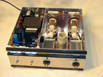
Personally, if there were a difference, it would probably be too small for me to even notice or care much about. I built a cathode driven RF amplifier with two 813's (w/metal plates, which I had on hand) and it easily produces 500 watts output with about 2KV on the plates. If I needed to replace the tubes, which I probably never will, I'd get whichever version I could find cheaper. Maybe I'm easy to please... or just cheap.
With either plate material, the 813 is a fantastic tube design that has stood the test of time and abuse, and has a well-earned place in Tube History (and a beautiful glowing directly heated cathode). Who could want more?
If indeed there is any difference in the way each "sounds" it would be subjective to the individual listener. The only way to know which you prefer would be to try both. From what I've heard and read on this subject, the metal plate version is often preferred by those who use the 813 for audio while the graphite plate version is preferred for RF use. The graphite plates are said to be able to withstand overload conditions for a longer (but still brief) time, which often occurs during the tuning of RF amplifiers.
Personally, if there were a difference, it would probably be too small for me to even notice or care much about. I built a cathode driven RF amplifier with two 813's (w/metal plates, which I had on hand) and it easily produces 500 watts output with about 2KV on the plates. If I needed to replace the tubes, which I probably never will, I'd get whichever version I could find cheaper. Maybe I'm easy to please... or just cheap.
With either plate material, the 813 is a fantastic tube design that has stood the test of time and abuse, and has a well-earned place in Tube History (and a beautiful glowing directly heated cathode). Who could want more?
Attachments
navidstat,
In my earlier post, I did some Estimates of 813 plate resistance, etc., based on the various specs of pentode operation. Not fully accurate, but enough to get started. One problem with doing it that way is that when you have an output transformer wound, you can not change the primary impedance.
The tube curves that PRR gave links in post # 17 gives a more accurate picture of the 813 characteristics in triode mode.
There is no one set of operating conditions that will give optimum performance, because output power, damping factor, distortion, etc., each interact with each other. Optimize one of those, and another will get worse.
In single ended operation, there generally is not complete cancellation of the 2nd harmonic accomplished by choosing a driver tube, operating conditions, and the output tube operating conditions, and output transformer primary impedance.
I understand you personally want that 2nd harmonic distortion (but for someone who wants to really cancel the 2nd harmonic, push pull is the way to go. With single ended, you get what you want, 2nd harmonic distortion).
Even if a single ended amp has 2nd harmonic somewhat cancelled when connected to a resistor load, then when you connect a loudspeaker, you will have varying impedance versus frequency. And for single ended amplifiers with different load impedances the cancellation of the 2nd harmonic goes away.
With push pull, the output stage is balanced in both the positive and negative alternations. A varying loudspeaker load impedance versus frequency will primarily change the 3rd harmonic in that case, not the 2nd harmonic distortion.
As to what driver tube and operating conditions to use, one of the most important factors is to be sure that the driver will not clip when it drives the output stage. Whether it is a triode or pentode driver, you do not want it to clip; it has to be able to cleanly output a large enough voltage swing that is 2X the output tube bias voltage.
I do not remember ever using a cathode follower between a driver tube and the output stage. I do not use A2 operation. And if you have a large bias voltage in the output stage grid, most tubes will not work as a cathode follower without violating the filament to cathode max voltages (twice the bias voltage). With 1000V and 110mA, if I am reading the triode curves of post #17 properly, the grid bias is -100V. The cathode follower would have to drive from + 100V to - 100V (200V peak to peak). Then there is the possible hum that may come with an unbypassed cathode (cathode followers can not have a cathode bypass cap) A2 does require a low impedance to drive the output stage control grid. That can be a cathode follower or a low resistance plate, rp driving an interstage transformer. A1 only requires an impedance that can drive the output stage grid resistor, and control grid miller capacitance (that is easy versus going with A2 operation). I select a driver stage that can work directly into the output stage in A1.
Other designers will use a cathode follower, other circuits, etc. And they will make it work great. We all have our own preferences.
Have fun designing and building. And of course, have fun listening.
Last edited:
Yes, of course. This is true. 'Cause this is the tube roller's credo 🙄.There is a difference in sound otherwise there is no need for tube rolling.
It depends, I'd say. The metal plate 813's are for plain Metal, the graphite plate ones are for Gothic or Doom Metal 🙄🙄🙄.Is there any difference between metal plate 813 and graphite plate sound?
Metal plate is cubic and graphite is a round rectangle.
Best regards!
There "might" be more secondary electrons coming off of the metal plates, and less secondary electrons coming off of the carbon plates; and there "might" not be.
For an RF tube grid in A2 that is going to be driven hard enough to have several tens of mA, or hundreds of mA, who cares if there are some secondary electrons landing on the grids. The driver is able to drive high currents into the output tube grid circuit.
But for the same tube in A1, for an audio application, you might care. The presence of grid current in A1 may show the difference of metal and carbon plates, if there is any. There should not be any appreciable grid current with the driver swinging negative by an amount equal to the negative bias, and then not any appreciable grid current when the driver swings the grid to just less than 0V.
i.e. with a driver output swinging from -89V to +89V (above and below the driver plate quiescent voltage), and then with that signal RC coupled to the output tube grid that is biased to -90V. Should not be drawing appreciable grid current (but secondary emission might cause grid current).
I would expect that if the actual tube curves varied by more than + or - 20% from the published curves, then you might want to get another 813. Both metal plate and carbon plate should be well within +/- 20%.
Years ago, I worked on multiple 1kW to 45kW 2-30MHz transmitters. Each transmitter model, and each type of tubes in them, had far less than 20% difference versus another of the same model. It is called quality control.
Last edited:
...or quality by design, I'd say. A good design should cope with tube ageing, not to speak of individual new tubes of the same type, but somewhat different manufacturing technologies. The performance of well designed gear shouldn't depend on imponderables.
Best regards!
Best regards!
- Status
- Not open for further replies.