I doubt that there will be any audible difference. Tubes doesn't reproduce sound, only amplify electrical signals, and sounds are acoustical waves.
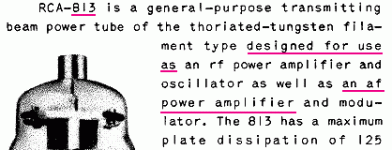
The 813 was a splendid VHF transmitting valve used in class C. It was not designed for audio use.
The 813 is one of the largest valves used in HF amateur radio. Classic amplifier designs from the late 1950s would squeeze 1,000 Watts PEP from a single device for SSB use. In class AB2 the input power for AM or CW would be 500 watts.
The valve base would be mounted on spacers so that a blower could be fitted under the chassis and a stream of forced air cooling would pass over the envelope.
The anode is 53 mm long and 48 mm wide. The metal is 1 mm thick.
The classic envelope is 60 mm in diameter, and excluding the base pins is 170 mm tall.
Last edited:
The datasheet of the Phillips qb2/250 (813) lists data for PP class AB and class B operation.
The best known commercial amp was made by Altec.
Not the typical SE tube, but it can work well that way.
About the sound of the metal box anode version I can only say it has a rattle sound: but that is because of the fragments of filament wire bouncing around when I shake it. No more life in that one I'm afraid 🙁
The 813 was a splendid VHF transmitting valve used in class C. It was not designed for audio use.
Attachments
Most conventional transmitting valves were intended for audio use too, perhaps as modulators or for high power PA. It may be true to say that they were not intended for hi-fi use. In some cases the datasheet gave figures for SE Class C RF and PP Class AB1 (or AB2) audio application. Someone wishing to use them for Class AB RF (as a linear PA) would have to work from the audio data.
With some study of the ratings, and careful amp design, you should be able to use the 813 in Beam Power mode, Ultra Linear mode, or Triode mode. But it probably would be best in pentode mode.
Just don't ask where the off-the-shelf in-stock output transformers are. The tube will get hot, even before you apply B+. The filament is 10V at 5A = 50 Watts!
Just don't ask where the off-the-shelf in-stock output transformers are. The tube will get hot, even before you apply B+. The filament is 10V at 5A = 50 Watts!
Pete Millett has designed and built an amp using the 813. You should checkout his pages at Pete Millett's DIY Audio pages
Where do you get an SE OPT for the 813?
I got almost everything i need to make an amp except the OPT. I am looking to use about 1100v B+ with switchable triode/pentode, tv damper diodes.
The datasheet of the Phillips qb2/250 (813) lists data for PP class AB and class B operation.
The best known commercial amp was made by Altec.
Not the typical SE tube, but it can work well that way.
About the sound of the metal box anode version I can only say it has a rattle sound: but that is because of the fragments of filament wire bouncing around when I shake it. No more life in that one I'm afraid 🙁
I got almost everything i need to make an amp except the OPT. I am looking to use about 1100v B+ with switchable triode/pentode, tv damper diodes.
There is a difference in sound otherwise there is no need for tube rolling. I listen now to SE 813 tube amp for more then a decade. I had RCA tubes but i like the shuguang fu13 ribbed plate best.
Look for output transformer at hammond.
Look for output transformer at hammond.
Attachments

Last edited:
Most conventional transmitting valves were intended for audio use too... Class C RF ....
As you almost imply: there are different types. In tuned RF amplifiers (distortion tuned-out) we can swing large peak grid current. Then a high-Mu type tends to need least grid drive *power*. In most linear audio we would strongly prefer zero or not-large peak grid current for minimum distortion in the driver. Now we want a low-Mu type which will give large current without large positive grid voltage.
Naturally the high-Mu types boast about their easy drive in class-C (RF) work, and the low-Mu types show C RF suggestions for convenience but also tout "audio". ("Convenient" in the sense that you may design with one type for both final audio and final radio stages for reduced stand-by inventory.)
Is there any difference between metal plate 813 and graphite plate sound?
Metal plate is cubic and graphite is a round rectangle
I can buy both of them with very good low price but only RCA.
Metal plate is cubic and graphite is a round rectangle
I can buy both of them with very good low price but only RCA.
"There is a difference in sound otherwise there is no need for tube rolling." Opening a barrel of worms, an engineer would say circuit design has more influence on the amplifier's sound but there are advocates on both sides. The OPT will make far more difference, finding one won't be easy. Build the amp first and worry about valves when it's built.
Andy.
Andy.
I want to build it with cascode e88cc in first stage and cathode follower El803 and 813 as triode. OPT is hand making (my friend). What you think about this?
Carbon plate rca i find lifeless, metal plate is more dynamic.Is there any difference between metal plate 813 and graphite plate sound?
Metal plate is cubic and graphite is a round rectangle
I can buy both of them with very good low price but only RCA.
Last edited:
navidstat,
How many watts single ended do you want? If you have a low impedance driver, you can drive the control grid with current, and get more watts (A2). But you would have to either DC couple the cathode follower, or use an interstage transformer between the cathode follower and 813. You can not use RC coupling from the cathode follower to the 813, unless you stay in A1 (less power). A2 draws grid current and does not work properly with cap coupling.
More . . .
I like the idea of a triode wired 813 amplifier, but here are some things to consider:
813 triode wired, A1, no grid current:
The mu (u) is about 8.5 The Beam Power Transconductance is 3750 micro Mhos. So the plate resistance, rp in triode wired mode will be 2,267 Ohms or a little higher. You have to plan your output transformer accordingly.
The 10V x 5A filament is 50 Watts. The continuous Plate dissipation is 100 Watts. You probably should not exceed 100W, you are now using the 813 as an audio amplifier; you are not using it as an intermittent RF amplifier. Average power is the key to long life. Anyway, you now have 150 Watts in that glass envelope.
The maximum 813 screen voltage is 1,100V. That would be the maximum for the plate and screen, because they are tied together in triode wired mode (usually with a 100 Ohm resistor). I do not know if the 1,100 Volt rating is because of Arc over voltage considerations or not.
I can not find any triode mode curves of an 813, but here is an estimate of a starting place to try: Plate and screen voltage 750V, Control grid bias -65V, the plate plus screen current would be about 125mA, and the plate + screen dissipation would be about 94 Watts.
If the plate resistance, rp, is about 2,300 Ohms, and if the plate load is 3 x 2,300 = 6,900 Ohms: The gain would be 8.5 x (6,900/(6,900 + 2,300)) = 8.5 x (6,900/9200) = gain 6.375 6.375 x 65 = 414V peak. (414V peak)squared / (6,900/2) = 12.4 Watts rms. 750V + 414V = 1,164V peak, should be OK.
Just a conservative way to run the 813 in SE triode mode. Try it and see, you may get a little more wattage than that. A lower plate load impedance might get a little more wattage, but would be a lower damping factor.
6DJ8 / ECC88 in cascode driver:
The cascode stage output plate resistance, rp, is a very high impedance. So the impedance that is driving the 813 control grid equals the parallel resistances of the plate load resistor and the control grid resistor. That medium or high impedance has to drive the miller capacitance of the Triode wired 813.
And the cascode stage has to have a voltage swing of + /- 65V = 130V peak to peak. That is probably too much for a cascode wired 6DJ8 or ECC88.
If you want to use a 6DJ8 / ECC88 . . . I bet you could get just as much or more voltage swing; and you would get a lower output impedance from a single triode of a 6DJ8 / ECC88 by using an IXYS 900 current source as the driver plate load. And the driver 2nd harmonic distortion would partially cancel the 2nd harmonic distortion of the 813.
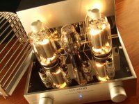
Light up the room with a pair of Thoriated Filaments of the 813 tubes!
How many watts single ended do you want? If you have a low impedance driver, you can drive the control grid with current, and get more watts (A2). But you would have to either DC couple the cathode follower, or use an interstage transformer between the cathode follower and 813. You can not use RC coupling from the cathode follower to the 813, unless you stay in A1 (less power). A2 draws grid current and does not work properly with cap coupling.
More . . .
I like the idea of a triode wired 813 amplifier, but here are some things to consider:
813 triode wired, A1, no grid current:
The mu (u) is about 8.5 The Beam Power Transconductance is 3750 micro Mhos. So the plate resistance, rp in triode wired mode will be 2,267 Ohms or a little higher. You have to plan your output transformer accordingly.
The 10V x 5A filament is 50 Watts. The continuous Plate dissipation is 100 Watts. You probably should not exceed 100W, you are now using the 813 as an audio amplifier; you are not using it as an intermittent RF amplifier. Average power is the key to long life. Anyway, you now have 150 Watts in that glass envelope.
The maximum 813 screen voltage is 1,100V. That would be the maximum for the plate and screen, because they are tied together in triode wired mode (usually with a 100 Ohm resistor). I do not know if the 1,100 Volt rating is because of Arc over voltage considerations or not.
I can not find any triode mode curves of an 813, but here is an estimate of a starting place to try: Plate and screen voltage 750V, Control grid bias -65V, the plate plus screen current would be about 125mA, and the plate + screen dissipation would be about 94 Watts.
If the plate resistance, rp, is about 2,300 Ohms, and if the plate load is 3 x 2,300 = 6,900 Ohms: The gain would be 8.5 x (6,900/(6,900 + 2,300)) = 8.5 x (6,900/9200) = gain 6.375 6.375 x 65 = 414V peak. (414V peak)squared / (6,900/2) = 12.4 Watts rms. 750V + 414V = 1,164V peak, should be OK.
Just a conservative way to run the 813 in SE triode mode. Try it and see, you may get a little more wattage than that. A lower plate load impedance might get a little more wattage, but would be a lower damping factor.
6DJ8 / ECC88 in cascode driver:
The cascode stage output plate resistance, rp, is a very high impedance. So the impedance that is driving the 813 control grid equals the parallel resistances of the plate load resistor and the control grid resistor. That medium or high impedance has to drive the miller capacitance of the Triode wired 813.
And the cascode stage has to have a voltage swing of + /- 65V = 130V peak to peak. That is probably too much for a cascode wired 6DJ8 or ECC88.
If you want to use a 6DJ8 / ECC88 . . . I bet you could get just as much or more voltage swing; and you would get a lower output impedance from a single triode of a 6DJ8 / ECC88 by using an IXYS 900 current source as the driver plate load. And the driver 2nd harmonic distortion would partially cancel the 2nd harmonic distortion of the 813.
Light up the room with a pair of Thoriated Filaments of the 813 tubes!
> can not find any triode mode curves of an 813
https://i1.wp.com/www.bartola.co.uk...loads/2015/05/813-SE-Class-A1-Za11k-Po20W.png
813 triode SE with 4P1L Pentode – Bartola(R) Valves
https://i1.wp.com/www.bartola.co.uk...loads/2015/05/813-SE-Class-A1-Za11k-Po20W.png
813 triode SE with 4P1L Pentode – Bartola(R) Valves
PRR,
Thanks for the links.
Having triode curves makes it easier for me to design.
Now all I need are parts and the time to design and build. I probably won't use another person's circuit. I would rather design on my own, even if it is not optimum, just more fun.
Thanks for the links.
Having triode curves makes it easier for me to design.
Now all I need are parts and the time to design and build. I probably won't use another person's circuit. I would rather design on my own, even if it is not optimum, just more fun.
6A3sUMMER:
Thank you for very complete and useful help.
Thank you for formula and calculation of anode rp and chock …
First thing: wattage is no matter at all. I want pure sound on A1 not A2.
I think 900V and 110mA is enough and good choice.
Second: I don’t want to eliminate second harmonics; I like them… thus using pentode tubes like E186F or D3a is better idea than using e88cc in cascade mode?
Do you have better choice for cathode follower tube instead of EL803?
Last edited:
- Status
- Not open for further replies.
- Home
- Amplifiers
- Tubes / Valves
- Best sounding RCA813