Ok, here's a cheat-sheet for you to start with (this addresses a closed box):
Qm is the mechanical damping factor: it is unaffected by the coil, so take the spec value.
Qe is the electromagnetic damping factor: this is affected, but you'll need the spec value for starters.
Qe is 2(pi)fMR/(Bl)² [two times pi times f times M times R] divided by [(Bl) squared]
The latter term of the equality is constant in your case, so take the values from spec and calculate the resulting number (make sure you use proper units). Alternatively, you can take Qe and Rdc from spec and calculate this constant directly. Under normal circumstances, the numerical result should be the same either way!
Let's call this constant number K. Then Qe = KR, whatever R is.
Step 2. R will go up (from whatever B139's spec Rdc is) to a new sum that includes all series resistance, including amp, cabling, the coil, etc. By taking the spec Qe, which uses the Rdc as is, and adding various resistances, you can calculate a table of new Qe's with various R values: starting from spec Rdc and moving upwards --say in steps of 0.5 Ohms to begin with-- and ending with your present system values, old coil included. If you think that steps of a half an Ohm are too coarse, use smaller ones (hint: no need really). Tabulate each resistance value with its corresponding Qe next to it.
Step 3. Then calculate total free-air Q: 1/Q = (1/Qm) + (1/Qe)
Step 4. Continue tabulating: write down these new Q values in a new column next to their corresponding Qe's from step 2.
Our table has three columns now: 1st column is resistances, starting from the B139's spec Rdc and going up in steps of 0.5 Ohm. 2nd column starts with spec Qe and goes up as calculated. 3rd column lists total Q's as calculated from the previous formula.
Step 5. Divide Vas (the woofer's "Volume of equivalent compliance", from spec) by Vb (the net inside volume of the box you have: has to be measured/calculated). This ratio equals (Qtc/Qts)² - 1.
Qts is the free-air Q mentioned above (we called plain Q for simplicity''s sake). Qtc is the Q of the in-box resonance. It's higher, because of the extra springiness of the air trapped in the box.
Step 6. Solve the equation from Step 5 for Qtc and tabulate them Qtc's in yet another column, the 4th in your table. Qtc represents the total damping of the system, including electromagnetic damping, suspension damping, and air damping.
This way you will identify the ballpark area your damping factors will be in.
The highest damping (lowest Q) is theoretical, because it presupposes an amp output, cabling and coil with zero resistance. It is at the top of your table.
The lowest damping (highest Q) represents your current situation. It is at the bottom of your table.
Look up textbook tables and graphs for frequency response shapes and transient response shapes for the range of Q's you have tabulated. There are plenty around.
This will show you what you'll get for your all-out effort to use a very low resistance coil.
Then make your choice of coil resistance.
*I just read you use a transmission line. If you know the new resonance frequency of the B139 now that it's mounted on the TL, you can calculate "Qtc" easily, because the ratio of in-box to free-air Q's is the same as the ratio of in-box to free-air resonance frequencies. This can take the place of Step 5. It is not very precise for a TL, but it will help you solve the coil multilemma.
Qm is the mechanical damping factor: it is unaffected by the coil, so take the spec value.
Qe is the electromagnetic damping factor: this is affected, but you'll need the spec value for starters.
Qe is 2(pi)fMR/(Bl)² [two times pi times f times M times R] divided by [(Bl) squared]
- f is the woofer resonance frequency in free air
- M is the moving mass and
- (Bl) the force factor of the magnet.
- All come from spec (although some can be measured and others calculated).
- (pi) is 3.1415926....
The latter term of the equality is constant in your case, so take the values from spec and calculate the resulting number (make sure you use proper units). Alternatively, you can take Qe and Rdc from spec and calculate this constant directly. Under normal circumstances, the numerical result should be the same either way!
Let's call this constant number K. Then Qe = KR, whatever R is.
Step 2. R will go up (from whatever B139's spec Rdc is) to a new sum that includes all series resistance, including amp, cabling, the coil, etc. By taking the spec Qe, which uses the Rdc as is, and adding various resistances, you can calculate a table of new Qe's with various R values: starting from spec Rdc and moving upwards --say in steps of 0.5 Ohms to begin with-- and ending with your present system values, old coil included. If you think that steps of a half an Ohm are too coarse, use smaller ones (hint: no need really). Tabulate each resistance value with its corresponding Qe next to it.
Step 3. Then calculate total free-air Q: 1/Q = (1/Qm) + (1/Qe)
Step 4. Continue tabulating: write down these new Q values in a new column next to their corresponding Qe's from step 2.
Our table has three columns now: 1st column is resistances, starting from the B139's spec Rdc and going up in steps of 0.5 Ohm. 2nd column starts with spec Qe and goes up as calculated. 3rd column lists total Q's as calculated from the previous formula.
Step 5. Divide Vas (the woofer's "Volume of equivalent compliance", from spec) by Vb (the net inside volume of the box you have: has to be measured/calculated). This ratio equals (Qtc/Qts)² - 1.
Qts is the free-air Q mentioned above (we called plain Q for simplicity''s sake). Qtc is the Q of the in-box resonance. It's higher, because of the extra springiness of the air trapped in the box.
Step 6. Solve the equation from Step 5 for Qtc and tabulate them Qtc's in yet another column, the 4th in your table. Qtc represents the total damping of the system, including electromagnetic damping, suspension damping, and air damping.
This way you will identify the ballpark area your damping factors will be in.
The highest damping (lowest Q) is theoretical, because it presupposes an amp output, cabling and coil with zero resistance. It is at the top of your table.
The lowest damping (highest Q) represents your current situation. It is at the bottom of your table.
Look up textbook tables and graphs for frequency response shapes and transient response shapes for the range of Q's you have tabulated. There are plenty around.
This will show you what you'll get for your all-out effort to use a very low resistance coil.
Then make your choice of coil resistance.
*I just read you use a transmission line. If you know the new resonance frequency of the B139 now that it's mounted on the TL, you can calculate "Qtc" easily, because the ratio of in-box to free-air Q's is the same as the ratio of in-box to free-air resonance frequencies. This can take the place of Step 5. It is not very precise for a TL, but it will help you solve the coil multilemma.
Thanks bbggg. Wow it's going to take me a day or two to get my head around all that information. And this is the 'cheat sheet' version?
A few questions come to mind:
do I use the metric measurement for M?
does R represent total resistance of amp/cables/inductor?
the tables and graphs for frequecy response shapes-are these specific to the B139 or universal?
I believe, but could be wrong here, that a transmission line does not add any extra air/box damping to the driver as it aims to present an 'infinite box' to the driver at all frequencies above the driver's fundamental resonance. If I am correct what figure do I use for Qtc?
I am sure I will have more questions after I digest it more fully.
Last edited:
And this is the 'cheat sheet' version?
")
Actually it doesn't matter because it is a proportionality factor, but sticking to consistent units always diminishes the possibility of error. Surely no one uses ounces outside of cooking recipes, or do they?do I use the metric measurement for M?
Yes, except in the case of the naked driver, obviously, Any ohmic resistance in series needs to be added in.does R represent total resistance of amp/cables/inductor?
Universal, that's why they tabulate "normalized" frequencies.the tables and graphs for frequecy response shapes-are these specific to the B139 or universal?
I guess it is, but it is the resonance itself we are concerned with here. If only air knew that what we want is to have it scoot down the line; alas it doesn't. I have the same concerns about the Qtc, that's why I included two methods of calculation. Alternatively you could just measure your woofer's resonance frequency: it is where resistance becomes maximum. For the B139 in a box I'd guess a very tall resistance peak somewhere around, oh, 40 Hz:I believe, but could be wrong here, that a transmission line does not add any extra air/box damping to the driver as it aims to present an 'infinite box' to the driver at all frequencies above the driver's fundamental resonance. If I am correct what figure do I use for Qtc?
HTGuide Forum - IMF Monitor Transmission Line Subwoofer
Here are two examples of how frequency response varies with total Q:
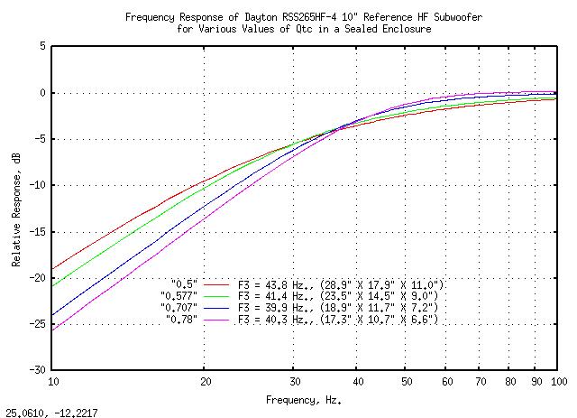

By using a coil with less resistance, Q will drop. What you will experience as a result is a leaner, drier frequency balance. The more so since you will gain a dB or so in midrange sensitivity. You may like this, or you may not. In the latter case you may put it right with the application of a subtle bass boost, either with a tone control, or by placing speakers a little closer to boundaries.
So, fewer losses mean less bass? Seems counterintuitive, but it isn't. The augmented bass response that results from higher Q's is due to ringing. This is what resonances do: they ring. This augmentation is the result of prolonged ringing in time, and shows up as a response hump only when added together in a steady state graph, like the ones above. When viewed in time slices, a high-Q resonance is slower to excite (that's "group delay") and even slower to decay. This can only be shown in anechoic impulse measurements, because of the long anechoic window needed to do such measurements.
The augmented bass response that results from higher Q's is due to ringing. This is what resonances do: they ring
An externally hosted image should be here but it was not working when we last tested it.
- Decay to baseline is the most rapid when Q=.5, the so called "critical" amount of damping. This alignment has a slightly drooping steady state frequency response.
- When Q=.707, return to baseline takes a bit longer, but response is "maximally flat".
- For larger Q's one can see the residual ringing that produces an increasingly larger response hump. This oscillatory decay to baseline is parasitic, i.e. its frequency is variable and not related to Fc, although it is always smaller than Fc.
- For Q's smaller than .5, decay to baseline is actually slower and very gradual, without overshoot, often described as asymptotic.
Great information there bbggg. It's surprising that a lower R inductor will produce less bass not more. I certainly don't want the mids to be any louder either. Haven't had much time lately to do those calculations but will do so as soon as I can. Thanks again for your input.
I would go to a motor rewinder and but a big bunch of heavy guage (work out guage on one of the many online inductor calcs) wire, make a spool and wind my own given the stratospheric 200dollar quote above!
I bought a 15 kilo spool of 1.5mm wire for 90dollars a few years back. You will need heavier guage than this, but that should not be hard to find.
Good luck!
I know copper prices have gone sky high over recent years, but that is really cheap!! I bought some 1.6mm wire just recently and it was $35 per kilo!! Maybe I should have asked what the price breaks were! I only wanted 2Kg.
8<------------------------------------------------------------------------------------------
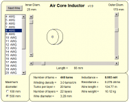
An easy to use inductor simulator is here --> Mark 2 - Inductor Sim The two coils I've made so far using this simulator for dimentions, were under by about 8% (luckily two of the inductors I need were actually pretty close to that value anyway).
but an 8.2mH air cored coil with a large enough gauge to get down to below 0.6 ohms is going to be pushing 3KG!
see the attachment for just how big (and impractical) an 8awg 8.8mH (I added 8% due to my experience of winding my own being lower than anticipated) inductor will be. Note that this isn't necessarily the optimal size, but it shows the point
Tony.
Attachments
Standard speaker theory available in any decent textbook, nothing fancy about it. Have you worked out a solution about coil gauge yet?Great information there bbggg
thats one big coil!I know copper prices have gone sky high over recent years, but that is really cheap!! I bought some 1.6mm wire just recently and it was $35 per kilo!! Maybe I should have asked what the price breaks were! I only wanted 2Kg.
8<------------------------------------------------------------------------------------------
An easy to use inductor simulator is here --> Mark 2 - Inductor Sim The two coils I've made so far using this simulator for dimentions, were under by about 8% (luckily two of the inductors I need were actually pretty close to that value anyway).
but an 8.2mH air cored coil with a large enough gauge to get down to below 0.6 ohms is going to be pushing 3KG!
see the attachment for just how big (and impractical) an 8awg 8.8mH (I added 8% due to my experience of winding my own being lower than anticipated) inductor will be. Note that this isn't necessarily the optimal size, but it shows the point
Tony.
Hi bbggg,
I must be making a mistake in my calculations because I'm getting a new Qe of 0.076 with a 2.3ohm inductor. Here's my working:
Qe / R = 2P x f x M / BI squared
0.4 / R = 6.285714 x 25 x 43.5 / 12.3 x 12.3
= 6835.714 / 151.29
R = (151.29 / 6835.714) x 0.4
= 0.02213 x 0.4
R (K) = 0.008853
then using Qe = K x R
total R = 6.2 (driver) + 0.05 (cable) + 0.008 (amp) + 0.3 (inductor)
= 6.558 ohm
then new Qe = 0.008853(K) x 6.558(R)
= 0.058 (for a 0.3 ohm inductor)
and new Qe = 0.008853(K) x 8.558(R)
= 0.076 (for a 2.3 ohm inductor)
Where am I going wrong?
You used grams instead of kilograms for moving mass, for one. According to the KEF spec sheet, moving mass is 54 grams (0.054 kg) and Rdc is 7.2 Ohms. There is a discrepancy between calculated Qe and spec Qe. I don't know if KEF include air load in their moving mass figure. Nowadays everyone does (it's probably a couple of grams or so) but that was then and this is now. In all probability your B139 has drifted somewhat off spec with time anyhow, but its mass and DC resistance should not have changed much. Try to redo the numbers, but keep in mind that addition of 0.358 Ohms of extra resistance is not going to make a big difference. 2.358 Ohms will, Qe will be 0.5177 then.
Last edited:
We seem to have different figures for the specs. I'm getting mine from the SP1044 spec sheet below ie.f=25hz, M=0.0435kg, DCR typical production spread=6.2ohm, Qe=0.40.
Strangely when I use these figure in the equation:
Qe = 2 x pi x f x M x R / BI squared
= 6.2857 x 25 x 0.0435 x 6.2 / 12.3 squared
= 42.3813 / 151.29
= 0.28 which is not the given figure for Qe of 0.40
but when I use your figures for M and RCD of 0.054kg and 7.2ohm
Qe = 6.2857 x 25 x 0.054 x 7.2 / 12.3 squared
= 60.818 / 151.29
= 0.40 which is same as given spec for Qe.
So if I use your figures in the equation:
(6.2857 x 25 x 0.054) x R = Qe
then, (0.05609) x R = Qe
therefore 0.05609 x 9.558(new R) = 0.54(new Qe) (you got 0.5177)
Where did you get your specs for the B139? Also I take it that a Qe of 0.71 is ideal, but to get to this figure the inductor would have to have a R of 5.36ohm. Is this correct?
rabbitz: perhaps, but I'm now curious about this method of working it out-it will help me understand things a bit better.
Attachments
I got it here:
Qe will not be your final arbiter, you have to factor in Qm to get Qt, and then you have to factor in the box to get Qtc. I happen to consider total alignment Q from .5 to .58 as "ideal", provided the drooping response can be corrected. The former has optimal damping, the latter has minimum group delay, or so the books say. If absolutely impossible to somehow equalize, then go for .7, keeping in mind that a better-damped (lower Q) system may benefit from locating closer to walls etc.
System Q choice is a multifactorial exercise that includes response, availability and feasibility of EQ, group delay, in-room placement, boundary reinforcement, and so on.
If I find some spare time later today, I'll do some calculations on both spec sheets mentioned.
Whether this or your own spec sheet matches your driver better......beats me! Maybe you should investigate if there have been different versions of the B139 over the years and see which particular one you have - and hope it's not age-drifted too far from spec! The small discrepancy on Qe was probably a small mistake I made with some decimals. Ideally you should measure Fc of the driver [as mounted on the box] with a freq. generator and multimeter, but not everyone has such equipment available.
Qe will not be your final arbiter, you have to factor in Qm to get Qt, and then you have to factor in the box to get Qtc. I happen to consider total alignment Q from .5 to .58 as "ideal", provided the drooping response can be corrected. The former has optimal damping, the latter has minimum group delay, or so the books say. If absolutely impossible to somehow equalize, then go for .7, keeping in mind that a better-damped (lower Q) system may benefit from locating closer to walls etc.
System Q choice is a multifactorial exercise that includes response, availability and feasibility of EQ, group delay, in-room placement, boundary reinforcement, and so on.
If I find some spare time later today, I'll do some calculations on both spec sheets mentioned.
Hi Alspe, the DIY crossover plans I used do not specify the resistance of the inductors (ETI Transmission line). The inductor I currently use which was wound for me has a resistance of 2.4ohm and I think the wire size is too small for a 8.2mH.
After living with the speaker for many years it is my personal preference to have slightly more bass and I assume if it is too much with the new inductor I could add a resistor in series with the coil. I am planning to learn how to use a crossover simulation program so I can plug in these different values and see how they effect the overall response.
Pay attention with that. No speaker requires the use of series resistor, you can understand why, they are implemented in the coil. You would need a super 100W resistor. You are fine playing/testing the right inductors only. A resistor only for testing w/low power.if it is too much with the new inductor I could add a resistor in series with the coil.
Thanks for all the info and would like to see your calculations if you get the time. Would like to get to the stage of being able to measure speakers one day.I got it here:
Whether this or your own spec sheet matches your driver better......beats me! Maybe you should investigate if there have been different versions of the B139 over the years and see which particular one you have - and hope it's not age-drifted too far from spec! The small discrepancy on Qe was probably a small mistake I made with some decimals. Ideally you should measure Fc of the driver [as mounted on the box] with a freq. generator and multimeter, but not everyone has such equipment available.
Qe will not be your final arbiter, you have to factor in Qm to get Qt, and then you have to factor in the box to get Qtc. I happen to consider total alignment Q from .5 to .58 as "ideal", provided the drooping response can be corrected. The former has optimal damping, the latter has minimum group delay, or so the books say. If absolutely impossible to somehow equalize, then go for .7, keeping in mind that a better-damped (lower Q) system may benefit from locating closer to walls etc.
System Q choice is a multifactorial exercise that includes response, availability and feasibility of EQ, group delay, in-room placement, boundary reinforcement, and so on.
If I find some spare time later today, I'll do some calculations on both spec sheets mentioned.
Ah OK, no resistors in the woofer section - thanks Inductor! Makes sense (now).Pay attention with that. No speaker requires the use of series resistor, you can understand why, they are implemented in the coil. You would need a super 100W resistor. You are fine playing/testing the right inductors only. A resistor only for testing w/low power.
Last edited:
Yes, none whatsoever. Woofer efficiency is far too precious to waste.no resistors in the woofer section
Regardless of the coil affair, you stated you'd like a bit more bass from your system. Assuming you have no tone controls to use, you could try this: move your speakers closer to the side walls and toe them in severely, so that their axes cross about a foot or so in front of the listening position.
There seem to be two spec sheets in circulation, one that I found posted at the HT Guide forum, and another one that you posted, metako. Both look genuine and the one you found looks more recent than the one I found (I base this educated guess on page layout and on fonts!) Let us just hope they are the only ones!
There are differences and similarities in parameters listed. Most importantly, moving mass differs (54 vs. 43.5 grams), as do mechanical resistance (1.43 vs. 1.24 mechanical Ohms), and mechanical compliance (7.43 vs. 9.3, both in 10^-4 m/N), which naturally changes Vas (127 vs. 164 liters). {Bl} dies not change a lot (12.5 vs 12.3 N/A, but keep in mind that {Bl} always enters alignment equations squared, and even small differences get somewhat magnified). There is also a drop in DC resistance, while magnetic flux is unchanged (i.e. magnet's the same). Hmmmm, now how can we put all this together??
My take, and I might be mistaken, is this: KEF had (or chose) to switch materials in the middle of production. Most probably this had to do with surround material. Either they found a more trustworthy supplier or a better polymer that they decided to go with. This skewed several parameters off the original specs, and KEF had to tweak the other parameters to bring driver behavior roughly back to where they thought it should be at that time. The new suspension being slightly softer and less lossy, they knocked a few grams off moving mass and/or unwound a few turns off the copper wire voice coil -hence the slight drop in {Bl}, a reduction in moving mass and in DC resistance- so as to keep the two major parameters (Fs and Qts) the same (25 Hz and 0.37, respectively). This provided a significant degree of before-and-after consistency.
End of detective story. I urged you to try and measure your woofers, but I understand this needs suitable equipment. One measurement that might tell you which version you have is a straightforward DC resistance measurement, easily done with a plain multimeter with no risk to the woofers. Is it 7.2 or 6.2 Ohms? This should tell you which version you have. From then on I would advise you to just use the Qe value from the relevant spec sheet, and not bother with its calculations at all. Do not bother with K either. Since Qold/Rold = Qnew/Rnew,, just solve for Qnew and you're home free.
Of the other parameters, the one most likely to have drifted is mechanical suspension, in both its compliance and mechanical resistance, which necessitate that Qm has also drifted. Which way and how much? Impossible to tell without proper measurement. The silver lining is that mechanical Q contributes little to overall Q, as it is the larger number which then becomes the smaller because it gets inverted.
This should be enough to orient you.
Really makes you think about gong active.
Briefly - then I consider the loss of SQ by introducing grungy op amps and lossy ceramic capacitors into the sound path or worse, yet, cheap digital eq's, and I come right back to passive. whoever mentioned going 0.1 or 0.05 Rdc is about where I am at - speaker cable is likely to be higher than that. I wind my own large value air cores - in fact I wound them all for all eight of my HT speakers and saved big bucks - only took about 3 evenings part time. A quick way I have to make my round wire inductors sound better than those on the market is to 'pot' them in CA glue afterwards.
Last edited:
I measured the B139s and both came in at 6.9ohms (7.2ohms minus residual resistance of the multimeter and probes of 0.3ohms) so I guess this is closer to 7.2 than 6.2. Good to know which set of specs my drivers are closer to. I will learn how to measure drivers fully as they obviously change over time or are different from spec at the outset. Thanks again, bbggg.
What is 'CA glue' Thoriated? Some sort of epoxy?
What is 'CA glue' Thoriated? Some sort of epoxy?
- Status
- This old topic is closed. If you want to reopen this topic, contact a moderator using the "Report Post" button.
- Home
- Loudspeakers
- Multi-Way
- Best inductor type for B139