Hi Gustavo, the 2A3 has a U (gain) of 4 or so and the 300B is not far behind that. And the GM70 has a U of 5, so 4x5=20. That is not much gain. The 12HL7 I am using has a U of about 100 so that is 100x5=500. From all I've read and talked to folks, a gain of 20 will not work. The put that to the real world, I divide my gain of 500 by 33 (into my output transformers (this is just an approximation) and get a watt per channel of 15wpc. Using your gain of 20, it would be .6 WPC. Of course, I don't know what I am doing....just learning myself. Maybe some one else can jump in. Cheers.
Last edited:
Hello DJN,Hi Gustavo, the 2A3 has a U (gain) of 4 or so and the 300B is not far behind that. And the GM70 has a U of 5, so 4x5=20. That is not much gain. The 12HL7 I am using has a U of about 100 so that is 100x5=500. From all I've read and talked to folks, a gain of 20 will not work. The put that to the real world, I divide my gain of 500 by 33 (into my output transformers (this is just an approximation) and get a watt per channel of 15wpc. Using your gain of 20, it would be .6 WPC. Of course, I don't know what I am doing....just learning myself. Maybe some one else can jump in. Cheers.
I assume you are running a sole GM70 drive by a 12HL7, so seems this 12HL7 Pentode is a powerful tube, and yet you have only 15W.
Certainly your GM70 tube will last a century, this is very good however.
Do it is possoble to get 25W output with this 12HL7??
I see the GlowMaster SEP 70W per channel at: SACThailand
they use a ''NOS 6N1P dual triode to input stage'' and a ''NOS 6BL7 large size medium mu twin triode in special anode choke loaded circuit can meet such demand of GM-70'' in the driver stage.
A poster in other Forum said the GlowMaster price is around 5Kusd, IF this is true it is a low price indeed.
I wonder what is an ''CHOKE LOADED CIRCUIT'' after all?? I see this terminology everyday...
Regards, Gustavo
Last edited:
From what I know, choke loaded is when there is a choke between the B+ and plate instead of a resistor. I am still a little confused on this point, but there is a difference between what gain does and what higher B+ does. I could get more wpc (like 25wpc) if my B+ was 1200v. The output of that tube is 125 watts so you take 1/5 of that for a hifi amp as max WPC, but that is at max B+.....in this case 1200v. I am running a B+ of 840v so it reduces from there. Now here is were the confusion sets in: The SWAG forumula on gain x gain / by the ratio of the OTs work out well. GO figure.
Do your amp use a Choke??From what I know, choke loaded is when there is a choke between the B+ and plate instead of a resistor. I am still a little confused on this point, but there is a difference between what gain does and what higher B+ does. I could get more wpc (like 25wpc) if my B+ was 1200v. The output of that tube is 125 watts so you take 1/5 of that for a hifi amp as max WPC, but that is at max B+.....in this case 1200v. I am running a B+ of 840v so it reduces from there. Now here is were the confusion sets in: The SWAG forumula on gain x gain / by the ratio of the OTs work out well. GO figure.
Wonder IF physically this part ''CHOKE'' is a transformer or an Voltage Double Circuit?
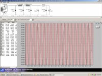
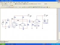
I have two chokes in my Power supply. But none in the signal path. Here is a pix of my power supply and a pic of the signal path schematic I am using. I still have to mess with the voltages a bit but it is basically there.
Post a couple pix of the choke you are talking about. It is most likely a two legged choke as I've never heard of a choke and PT in the same can. Cheers.
Post a couple pix of the choke you are talking about. It is most likely a two legged choke as I've never heard of a choke and PT in the same can. Cheers.
Attachments
Hi Gustavo, hi all,
I'm on holiday, not able to access internet very often.
RC coupling is resistor-capacitor coupling, where you have a resistor from B+ to the plate of the input tube, then a capacitor from that junction going to the next stage. If you change the resistor into a special 'plate choke' with very high inductance, then you get a 'choke-loaded' design which can have higher gain.
I don't know much about the circlotron, but I don't think it's the easiest topology for a first tube project. SE with cathode bias is by far the easiest stage to build -- it is automatically stable without any adjustments or fiddling.
If you use high-efficiency speakers, one GM-70 will give you enough power to shake the walls! My best advice I can give is, to keep it simple, but finish the project with success, rather than having a very complicated project which never gets finished (I've ended up in this situation too often! 🙂 )
Best regards,
Kenneth
- Status
- Not open for further replies.
- Home
- Amplifiers
- Tubes / Valves
- Best GM70 version suited for audio??