! said:
L or R is a potential difference to virtual ground voltage level. Just as either channel has to generate that voltage precisely, the ground has to, as precisely, maintain the difference.
The railsplitter is to tie the mid-point supply reference to signal ground, but then the buffer to isolate it by dumping the output current back to the rails instead of the reference from the railsplitter. For each L or R channel *action*, the ground buffer channel has to react to maintain the drive voltage through the load.
I'm definitely interested in knowing what effect a discrete ground buffer has in a PIMETA. One small bit of evidence that indicates that it isn't essential is Tangent's opinion that stacking the ground buffers doesn't seem to affect the sound much. I'm not sure how buffers and headphones interact, but I suspect that the power that is converted into audio in the headphones might have something to do with this supposed 'lighter duty' of the ground buffer.
Myself, I'm curious. I've got a few Millett DB boards waiting to be built, going to try them in a PIMETA. I'm going to start with a BUF634 ground, and then see what happens if I manage to cram a discrete buffer into the ground channel.
Ryssen said:Ok,so for best result the ground channel buffer should be changed to?
But it will work anyway?
Over at head-fi.org, there's a thread by nate_maher IIRC. He built a diamond buffers on PCBs intended for the Millett tube hybrid headphone amp. He used a single BUF634 in the ground channel. It worked, and as far as I could see, it was a pretty nice improvement over L/R BUF634s.
Ok,tell us how it sounds then..🙂I'm going to start with a BUF634 ground, and then see what happens if I manage to cram a discrete buffer into the ground channel.
kristleifur said:
I'm definitely interested in knowing what effect a discrete ground buffer has in a PIMETA. One small bit of evidence that indicates that it isn't essential is Tangent's opinion that stacking the ground buffers doesn't seem to affect the sound much.
I never said it was "essential", if we're splitting hairs like this then a discrete buffer isn't at all essential for L & R channels either.
It is not necessarily evidence against using a discrete in ground to not stack, It would be more similar to say that if you are using a discrete buffer in the ground and someone felt BUF634 didn't need stacked, then you don't need to use paralleled output transistor pairs on the discrete buffer you use for ground. Accordingly, most people don't use paralleled output transistors, I recall Sijosae made a layout for one like that but I suspect it was more a matter of an option to add current handling when working with only TO92 transistsors as he likes everything so wonderously small.
I'm not sure how buffers and headphones interact, but I suspect that the power that is converted into audio in the headphones might have something to do with this supposed 'lighter duty' of the ground buffer.
Ground is a channel. Just like L and R. While it is true you can do something different with ground because it will maintain a balance between left and right, what you do with ground will still effect both left and right. So if you are using particularly chosen buffers on L & R to expect some change, ground is the next logical step to change as well. Or you could do it just the opposite, keep L & R the same but a discrete ground. Some people feel these should match, if so then you want ground just like L & R. That was the point of having BUF634 on ground too when it was in L & R, that they be the same. If ground didnt matter then something cheaper or simplier than BUF634 might've been used instead, though it is easier to keep similarities in low-mid-level amp project that is potentially done by less experienced users who just use defaults as well as those who are on the next level and decide to modify.
Myself, I'm curious. I've got a few Millett DB boards waiting to be built, going to try them in a PIMETA. I'm going to start with a BUF634 ground, and then see what happens if I manage to cram a discrete buffer into the ground channel. [/QUOTE]
I don't understand why you would do this since it is no longer a manageable size. I mean Pimeta's charm is being small but IIRC the Millett DB boards won't fit in gnd will they? So some interesting maneuvers would have to happen to shoehorn it into the space available. The PPA2 is (although with a few more tweaks too,) the evolution of the Pimeta-with-discrete buffers topological design. OK, maybe just distant relatives as there was another version and the Meta42 in there too but they are similar enough to see a parody when talking about goind discrete on L & R in a Pimeta. Note it (PPA2) has discrete ground buffer. It could've just had a BUF634 or something else for it's ground.
I'll grant you that it is less difference sonically for Gnd than L or R, but it is along same goal as further improvement. If one is going to spend the time to tweak out Pimeta (which is another topic, depends on the goal maybe) it would be arbitrary to stop right before swapping the Gnd buffer to match L & R.
I think three of the Sijosae buffer boards should fit fine with the Pimeta.
I am also using the Linkwitz Crossfeed board, which will be mounted on aluminum spacers over the Pimeta board.
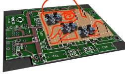
I was thinking the three buffer boards could be mounted on the same screw/spacers as the Linkwitz, but extending to the back instead of over the Pimeta. So the corners of two of them would be mounted, and then the third one connected between the two of them. They would be connected with wires run directly to the buffer pads on the Pimeta.
The pic is a little quick and dirty but -- I dunno, from looking at pictures of the diamond board it should work. It should fit fine in the 6" deep Hammond chassis I'm using, with room for the Tread behind it. They could be mounted upside down in this fashion, if need be.
I am also using the Linkwitz Crossfeed board, which will be mounted on aluminum spacers over the Pimeta board.
I was thinking the three buffer boards could be mounted on the same screw/spacers as the Linkwitz, but extending to the back instead of over the Pimeta. So the corners of two of them would be mounted, and then the third one connected between the two of them. They would be connected with wires run directly to the buffer pads on the Pimeta.
The pic is a little quick and dirty but -- I dunno, from looking at pictures of the diamond board it should work. It should fit fine in the 6" deep Hammond chassis I'm using, with room for the Tread behind it. They could be mounted upside down in this fashion, if need be.
Attachments
! said:I don't understand why you would do this since it is no longer a manageable size. I mean Pimeta's charm is being small but IIRC the Millett DB boards won't fit in gnd will they? So some interesting maneuvers would have to happen to shoehorn it into the space available.
Personally, I built the PIMETA as a learning experience, not really as a portable amp - so I'm free to try some interesting maneuvers for fun 🙂 I'd be surprised if the Millett buffer fits in ground without some coercion or trickery ...
When I said 'essential', I'm looking at things in a bit of corner-cutting, work-saving manner. The most bang for the buck, the most education and surprise out of the fewest steps taken. Poor choice of a word, really.
slowpogo said:The pic is a little quick and dirty but -- I dunno, from looking at pictures of the diamond board it should work.
Why does your robot only have 3 teeth?
😀 😀
It should fit fine in the 6" deep Hammond chassis I'm using, with room for the Tread behind it. They could be mounted upside down in this fashion, if need be.
Yes you should have room for that. I made a funnier picture of what I had though of doing before I gave up on a fancier buffer for Pimeta. Putting a daughterboard across 1/2 the top that sits on pin-stilts. I just hate backwards engineering a layout to get there, particularly when it could be as easy to just do a whole new board with more room for the buffers on the same plane, but then it gets a little closer and closer to a PPA2, and there were some people over at head-fi that were doing some interesting SMT work in a similar direction but I got caught up in other things and haven't followed that so much recently.
Attachments
I started with a http://www.pha.inecnet.cz/macura/buffer_en.html
And later added QRV5 instead of BUF634.
I do not regret no buying a PPA2 instead..😎
And later added QRV5 instead of BUF634.
I do not regret no buying a PPA2 instead..😎
I'm curious where the PPA2's better specs (greater dynamic range, lower noise floor and distortion) come from. Will using discrete diamond buffers in a Pimeta get it closer to the PPA2 in those terms?
(Weird, suddenly there's no "edit" button for my posts)
Also, the diamond buffers each have 200uf of electrolytic capacitance. Does this mean they're directly lightening the load of the rail caps? Or more to the point, will they offset some of the "slowness" of big 680-1000uf rail caps and contribute to "quicker" qualities like detail and imaging?
Also, the diamond buffers each have 200uf of electrolytic capacitance. Does this mean they're directly lightening the load of the rail caps? Or more to the point, will they offset some of the "slowness" of big 680-1000uf rail caps and contribute to "quicker" qualities like detail and imaging?
Not lightening the load really, more a matter of isolation.
On PPA2, the two small 'lytics for the opamp supply are attempting to attain, resulting in a cleaner supply for them. Suppose you start out with a theoretically perfect power supply for your amp (impossible of course, maybe even overkill to try for one on a Pimeta but for the sake of argument). If the opamps were the only active devices using power, there is no addt'l noise to get rid of, you'd only need the best local decoupling close to them as reasonably possible. In some amps a short feedback loop to the supply would help too so the supply can correct, but opamps are very fast and low current so the supply correction isn't much of a factor, at least not fast enough to realize cleaner power in an absolute sense.
Since there's another (relatively) larger active stage consuming more power, the buffers themselves, your theoretically perfect supply is no longer perfect because the buffer introduces noise into the supply rails. If you wanted to built an overkill tweaked PPA2, you could even isolate each buffer's supply, but since the buffer is a buffer, a slave to opamp control within a feedback loop, there is correction present and it makes less of a difference than the opamp supply.
By having the supply to the opamps behind their own railsplitter, JFET, resistor and caps, the only noise one *hopes* will remain is that produced by the opamp itself.
Just adding a discrete buffer to a Pimeta, your measurements aren't likely to change much from using BUF634. Remember that measurements and sound are two different things though, we can't ignore measurements but also know two amps with specs like THD or noise low enough it shouldn't be audible, may still sound different. Even so, if one is putting the time into the design it would seem you either want those improved or are deliberately trying for a certain type of distortion that's pleasant (tube amp for example).
I don't mean to imply a Pimeta with upgraded buffers won't sound better (depending on exact details of what/how it's done of course) than with BUF634, but putting something like a buffer on long leads when it has to have a feedback to the opamp will tend to introduce even more noise. Even PPA2 is not perfect in this, it's a shorter path but it could be tweaked to have ground planes on it.
I think the central point here could be, what the target for Pimeta was and whether going to a lot of work to make a Pimeta more PPA2-like, but not quite and with the detractions of remotely situated buffer, is going to reach the intended goal or just be a significant amount of work that is a bit redundant since Tangent and others already put in so much time in development to arrive at PPA2. It is certainly less DIY, less of a learning experience to just build by a pre-made design but it's intention was essentially what the goal is, an improvement of the general Pimeta topology with discrete buffers deemed good by those who developed them and successive users.
It is fun and interesting though, to take a set amp config like Pimeta and do your own thing to change it and see what the result is. With PPA2 you take it or leave it beyond a few parts choices. That's not "really" true to the extent you could design in whatever buffer you wanted same as with a Pimeta you just *plug* it in on the appropriate spots on the board, or could jumper out or otherwise modify the PPA2 design since it is easier to subtractively get rid of things on a board that could accomodate them, than to add things to a board that can't (Pimeta).
I like both Pimeta and PPA2, it's just my opinion that for a non-portable Pimeta-like amp with discrete buffers, a PPA2 is a better choice even if you just wanted to build it like a discrete buffered Pimeta on the PPA2 pre-made PCB by jumpering out the opamp rail isolation/etc - though since it's developed and provided for on the PPA2 board and is an improvement, so much the better.
I'm trying the diamond buffers simply because they cost the same, even a little less as the 634Ps. Cost is an issue for me. I've already got the Pimeta board, have everything worked out as far as what components to buy, etc. And I've already bought half of them. So at this point it doesn't make much sense to chuck all that effort, spend $18 for the PPA board and even more money and shipping on other components. Maybe next time 🙂
The longest lead for the buffers, as I intend to mount them, would be not quite three inches long. Most of the others would be a fair amount shorter. Is that so "long" as to introduce noise? The buffer boards do have a resistor to counter RF interference. The resistors I'm using are non-magnetic, if that matters.
The longest lead for the buffers, as I intend to mount them, would be not quite three inches long. Most of the others would be a fair amount shorter. Is that so "long" as to introduce noise? The buffer boards do have a resistor to counter RF interference. The resistors I'm using are non-magnetic, if that matters.
It will introduce noise but how much (or if you can hear it), I can't say. I would definitely build into a grounded (metal) case if I did it.
OK...the thing that puzzles me though, is that this buffer board was not made to plug into a socket, its In/Out and V+/V- pads are basically in the four corner areas. So by virtue of its very design, to use it at all with an amp would require leads of some length, no?
If leads are kind of a bad idea to begin with as you suggest, is the board's design just flawed, or am I missing something? How could you use it and not introduce noise?
I don't have the board(s) yet, but I'm also wondering, since nearly everything is surface mounted on it, might it be possible to use a conductive ink pen on the underside to converge the In/Out and voltage pads to an area where pins could be soldered on, thereby allowing it to be plugged into a DIP-8 socket?
slowpogo said:OK...the thing that puzzles me though, is that this buffer board was not made to plug into a socket, its In/Out and V+/V- pads are basically in the four corner areas. So by virtue of its very design, to use it at all with an amp would require leads of some length, no?
Just so we are on the same page, and to make it easier on those of us who are lazy (like me), would you link to this picture and maybe the schematic?
It is premature to guess but I'm wondering if the holes did correspond to some other amp board. If you have to use leads, you have to - but if so I would make them as short as reasonably possible. I'd even think about using coax and tying the shield to ground on the Pimeta PCB if it wasn't really short, but you can always try it however you want and then decide if it's ok for your ears.
If leads are kind of a bad idea to begin with as you suggest, is the board's design just flawed, or am I missing something? How could you use it and not introduce noise?
"Flawed" might be a moving target, all the time we make suggestions to one another about some ideal thing that may not matter in isolation, but several such things cumulatively make make for a better or worse amp. That's 1/2 of DIY, seeing if you find a difference. Some would say it is sub-optimal to have a buffer on a board at all, even with pin-headers to connect it, partly since it is not grounded then and no immediately adjacent supply decoupling (unless it's on the buffer you are referring to?).
To keep noise down you'd just keep the leads as short as possible, shielded wires and/or case.
I don't have the board(s) yet, but I'm also wondering, since nearly everything is surface mounted on it, might it be possible to use a conductive ink pen on the underside to converge the In/Out and voltage pads to an area where pins could be soldered on, thereby allowing it to be plugged into a DIP-8 socket?
I would imagine on a surface mount board there are a fair amount of traces on the back. I can't speculate whether extending them to any particular point would do well. I think if I were going to do that, I would take a DIP8 socket, stick pieces of small wire in that, soldered in, put a blob of epoxy on the board to secure it down then run those wires over to the appropriate spots. I have no confidence that conductive ink will be acceptible, you really want to avoid these kinds of odd paths in a feedback loop. That doesnt mean it won't work but I would be very hesitant to use a conductive pen trace.
Here's the link to the buffer info:
Per-Anders Diamond Buffer
Sounds like it has a large "ground plane" and with its own ground connection. Would this somewhat negate the need for shielded wire?
Per-Anders Diamond Buffer
Sounds like it has a large "ground plane" and with its own ground connection. Would this somewhat negate the need for shielded wire?
slowpogo said:Here's the link to the buffer info:
Per-Anders Diamond Buffer
Sounds like it has a large "ground plane" and with its own ground connection. Would this somewhat negate the need for shielded wire?
If you are going to use wires it may be better than some but it does seem to have traces on the back as you can at least see vias and not much of the copper paths on top (but it could just be covered and because of the odd angle I saw it). That doesn't negate the need for the shielding, the issue is the pickup on the long wires not the board (though any board ideally has ground planes too, but many buffer boards are smaller, it is more elaborate than most).
I think your doing this would be interesting, but personally I'd be more likely to just leave the BUF634 in a Pimeta or use a simplier buffer that can fit and plug directly into the socket, or use a more advanced amp that puts the buffer on the same board - but I've said that already. For the most part the components you would have to populate a Pimeta will also work to populate a PPA2, if you only wanted to jumper out the features it has beyond the discrete buffer and Pimeta circuits. But that's only me, what would really be interesting is if you had both and could compare them.
eeka chu said:
Funnily enough, I spent an hour or two listening to the AD843 and OPA637 side by side yesterday.
I've got to say, I think I actually prefer the AD843 from what I've heard so far.
The AD843 is snappier, clearer and more upfront.
I was planning on using the AD843, as I keep hearing great things about its sound. After reading the data sheet, however, I see it has a maximum supply rating of 18v. It's kind of weird that in several threads people have been quick to caution that the AD8620 can "only" handle 24v, but I've never seen such diligence regarding the 843's limitations.
Anyway, I'm using a Tread, so I can easily dial down the voltage. But this raises a few concerns...the unused voltage from my 24V wall wart will make the Tread really hot, correct?
And is 18v enough to get optimal performance out of the other components in the Pimeta, like the buffers, filter caps, etc.? I will have about 1500uf of filter capacitance total. Will 18 volts even run this amp?
slowpogo said:
I was planning on using the AD843, as I keep hearing great things about its sound. After reading the data sheet, however, I see it has a maximum supply rating of 18v. It's kind of weird that in several threads people have been quick to caution that the AD8620 can "only" handle 24v, but I've never seen such diligence regarding the 843's limitations.
You are jumping to unfounded conclusions. AD843 has a max of +-18V rail-to-rail, that's 36V total.
Anyway, I'm using a Tread, so I can easily dial down the voltage. But this raises a few concerns...the unused voltage from my 24V wall wart will make the Tread really hot, correct?
It would've made the Tread warmer, yes. Whether a problem depends on the total current consumed x voltage dropped versus heatsink on the Tread. A Pimeta is not normally a very power hungry amp, around 100mA for example, more or less, so dropping 10V on your regulator is only 1W, a modest sized heatsink would be all that's required but you don't mention the transformer and it's associated peak DC voltage so we could determine mathematically what the total drop on the linear regulator in a Tread would be. Tread puts the regulator at the board edge so a giant heatsink could be used if you really needed one, but as you see from the other details in my post, this isn't needed, you will not have to drop so much voltage and "might" not need a heatsink on the regulator at all, but I would put at least a small one on it just to be conservative.
AD843 has a higher Quiescent Current at ~ 12mA so unlike AD8620 and other more miserly opamps, it will feel mildly warm at 24V (as +-12V) but it's nothing to be concerned about at all and not what you asked about. In theory it's operation will drift some with this heating, it could be my imagination but in amps where I had AD843 and a tightly closed case, I thought the lower heat from lower, around 15-20V rail-rail, sounded a bit cleaner. Again I write it could be my imagination, but it definitely felt warmer, the power consumption is in relation to voltage when current is constant. It might not be a reason to change your present (previous) plans, you can try 24V and only change it if it seems important later.
And is 18v enough to get optimal performance out of the other components in the Pimeta, like the buffers, filter caps, etc.? I will have about 1500uf of filter capacitance total. Will 18 volts even run this amp?
LOL. 9V (+-4.5V rail-to-rail) will run the amp fine, with possible exception of some opamps that spec higher voltage into higher ohm load but that is not the load driving a buffer. Datasheets are your friend, when the AD843 sheet says it can use +-4.5V that means they guarantee it, in writing, to work. Same goes for the BUF634, but you are substituting a different buffer so if you need to know what it's minimum is you might ask it's designer, but I can tell you even without the schematic that it's lower than the opamp. These are not the concerns.
The 24V most people use is just an arbitrary and unnessary voltage to use, they are operating at a voltage that is a conservative maximum that's safe for "most" opamps. There is a reasonable logic in doing that, but not really to feel it's necessary in any way. The voltage swing from the Pimeta (any amp, really) as the signal output is governed by the supply voltage and how close to the rails the opamp and buffer can swing. How high a voltage you really need is determined by the headphones you use, their impedance which you don't mention, and of course the max volume you want the amp to output (up until the limits of the design).
In summary, 24V rail-to-rail is fine. If you can already make that happen, go ahead and use 24V. If you can't for some other reason (like battery power, too many cells to get that voltage), don't worry about it till you have specific cans that need it).
- Status
- Not open for further replies.
- Home
- Amplifiers
- Chip Amps
- Best buffer for PIMETA?