mart.s - yes, looking again you are right - there does seem to a direct connection from the mains input socket to the bolt (which presumably means it isn't double-insulated) . I think the only possible answer is either that the lower end of the bolt is insulated from chassis, or it isn't but the chassis itself isn't connected to the main grounding system. Maybe the chassis is simply used as an electrical screen, connected to ground via the bolt.
Need to know where those other wires go (from photo looks like there could be three?). Also, when you take the connection off the bolt, is there any continuity between chassis and any other part of circuit? Must solve this mystery - do let us know what you find when you open it up again.
Need to know where those other wires go (from photo looks like there could be three?). Also, when you take the connection off the bolt, is there any continuity between chassis and any other part of circuit? Must solve this mystery - do let us know what you find when you open it up again.
That's why it's a bit of a mystery. If the IEC earth is connected to chassis and to the top of the bolt then it completes a short-circuit between the top and the bottom of the bolt. That is a big problem - the first big no-no with toroidals is that you don't do this, because it acts as a short-circuited turn on the xformer - with a voltage induced magnetically, and a large current-capacity because it's a thick steel bolt. Then the xformer will be trying to put out more power than it was designed for (the proper secondary has thinner wires and much higher resistance - so limited current). That means it (not so much the earth wires) will seriously overheat and fail. I hope my explanation is correct - I'm no professional here!
mart.s, never mind the "where did this thing come from" comment. Even decent designers and manufacturers make mistakes.
Reasonable understanding of electricity is all it takes. If you stuff a conductor through the toroid core (even steel) and then make both ends meet from around the outside, you have a shorted turn. That's just how the transformer works.
This one gets by a lot of people now and then who should know. As has been discussed, there are special conditions where this might not turn out to be a big deal. But, you can fix it so everything works And nothing could go wrong, by not making electrical connections to that bolt.
MikeVou, smaller transformers like that might have less than a volt per turn, so if the conductors are long and thin enough, the shorted turn becomes a decent resistance relative to the supply voltage and might not create enough heat or power loss for anyone to ever notice!
But it's still there. The potential for signal level problems could be more severe. I'd just get rid of that bolt as a terminal. It's simple to do and fixes all the worries.
But it's still there. The potential for signal level problems could be more severe. I'd just get rid of that bolt as a terminal. It's simple to do and fixes all the worries.
Andrew - thanks for explaining that - it all helps an amateur like me!. I agree that there isn't any point in having the connection on the bolt, unless running the wires underneath the pcb is a problem for some reason, or unless there isn't room between chassis and pcb for a chassis-tag with a number of connections.
However, I still think mart.s must have re-assembled it as per original design, and presumably the Gramophone would have had something to say if the original design had serious problems. If it were mine, I would leave it and try it, rather than re-design it. In any case, none of this would affect the original output transistor problem IMHO.
However, I still think mart.s must have re-assembled it as per original design, and presumably the Gramophone would have had something to say if the original design had serious problems. If it were mine, I would leave it and try it, rather than re-design it. In any case, none of this would affect the original output transistor problem IMHO.
Damn.. I know what you mean now Guys, how could I be so dumb. So yes that IS a worrying design aspect.
Thanks Andrew it was when you mentioned the solid metal conductor core through the wound Toroid air core that turned the lights on.. Duhhh.
Thanks Andrew it was when you mentioned the solid metal conductor core through the wound Toroid air core that turned the lights on.. Duhhh.
If you look at the assembly of the amp, it is clearly aimed at lowest possible cost and the power wiring certainly fits in with that. It's a quick slap of cable-tied wires over the top of the box contents with no added fasteners. It should meet compulsory standards and apart making connections, that's all it has to do.
For the cost of using a dedicated chassis fastener for all safety earth connections, it could have followed a conventional, recognized layout and there would be no boggling over why it isn't. Certainly, a second earth lead there is more likely to be connected to the chassis below the PCB and MikeVou's suspicions would be justified.
I think it's just a case of being a cheap and simple assembly solution.
Last edited:
I think another big problem must be that unusual external case and overall shape. It's always interesting to think about how they have manufactured something like that, and how they have allowed for servicing access. It's difficult to tell just from those two photos, but the back panel we can see must be an integral sub-assembly with the pcb, since it's got huge rows of phono input, etc sockets on it (looking at the pics in Gramophone article). The front panel in mart.s's photos may be just a sub-panel carrying the switches and pot. So perhaps that whole assembly just slides into that curvy plastic sleeve casing (which includes the outer front panel) from the back end. Mart.s seems to say that there is a metal chassis, so perhaps that's just a flat metal plate below the PCB - it would need something like that to provide overall rigidity and to safely carry the weight of the xformer. If that's so, then the "chassis" wouldn't need to be a main ground for all the circuitry - the top of the xformer bolt could do that, with the chassis plate just "floating" at the voltage at the other end of the bolt. The pcb with front and back panels, sockets, controls, etc could then be removed for servicing by just disconnecting the grounding tags from the top of the bolt and removing a few fixing screws, leaving the xformer and power supply, etc in the case..
The things people will do for a "different" look!!
The things people will do for a "different" look!!
For what it's worth, I have a limited quantity of NOS aluminum case Motorola sub-1Mhz devices from the late 70s. They do sound a bit different from the steel case versions.
That unusual case is an injection casting, which allows for any shape you want (same as plastic).I think another big problem must be that unusual external case and overall shape. It's always interesting to think about how they have manufactured something like that,
Should be some aluminum alloy (good) or if they're cheap minded, some lower quality pot metal (Zamak or some relative).
As of the 2N3055 vintage, those ST seem to be the original ones, so replacement should be the same.
Thanks - interesting. Do you know if the front panel (with control markings) is a part of the casting?
I think another big problem must be that unusual external case and overall shape. It's always interesting to think about how they have manufactured something like that, and how they have allowed for servicing access. It's difficult to tell just from those two photos, but the back panel we can see must be an integral sub-assembly with the pcb, since it's got huge rows of phono input, etc sockets on it (looking at the pics in Gramophone article). The front panel in mart.s's photos may be just a sub-panel carrying the switches and pot. So perhaps that whole assembly just slides into that curvy plastic sleeve casing (which includes the outer front panel) from the back end. Mart.s seems to say that there is a metal chassis, so perhaps that's just a flat metal plate below the PCB - it would need something like that to provide overall rigidity and to safely carry the weight of the xformer. If that's so, then the "chassis" wouldn't need to be a main ground for all the circuitry - the top of the xformer bolt could do that, with the chassis plate just "floating" at the voltage at the other end of the bolt. The pcb with front and back panels, sockets, controls, etc could then be removed for servicing by just disconnecting the grounding tags from the top of the bolt and removing a few fixing screws, leaving the xformer and power supply, etc in the case..
The things people will do for a "different" look!!
All of the amp looks as though it is made from metal and aluminium, there is no plastic anywhere in the construction that I can see. The top and bottom panels appear to be made from steel covered in a crinkle effect paint. There are 6 small Allen screws on the bottom of the case which once removed allows the top and side outer shell part to be slid off backwards over the rear panel.
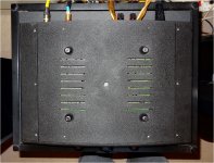
This leaves the front, back and circuit boards as one piece. To get to the under side of the circuit board you then have to remove the thin center bolt that goes through the top of the toroid AND bottom of the remaining case, you then remove the four long black screws that hold the main circuit board via ceramic standoffs/spacers to the curved bottom, the same long screws also hold the feet on. Now the bottom panel comes off exposing the under side circuit board. Of course once you have done this you need to support the toroid with one hand to flip it over and work on it (as it is now free to float about attached by a few wires) and the main circuit still board attached to the front and back. This is a tricky procedure because now the main circuit board is quite bendy and the front and back panels are thick and heavy. There is no other panel/shield directly under the circuit boards.
That is pretty much how I remember it to be when I last took it apart.
Picture is of underside.
Attachments
Last edited:
That means that the metal chassis (which has to be connected to AC mains ground to meet regulations) is only grounded to AC ground through the xformer bolt. I have to agree with others - I wouldn't do that, and would have taken it direct to chassis with a substantial fly-lead to the central ground or input grounds if they weren't already on the chassis.
As things are, it will mean that you will have a shorted "turn" on the xformer, but maybe as others on this thread have pointed out, that won't have a disastrous effect if the loop resistance (bolt connecting leads) isn't very low.
I have found that the effects of different grounding arrangements can be quite difficult to predict, even when you follow best practice. If that amp were mine, I would try it as it is (as the designer intended it), and see what it's like. If the designer tested it thoroughly, then the spec should be ok. Others on the thread are right - rerouting those bolt connections direct to the chassis somewhere shouldn't make things worse - but it may not make a difference either. But it remains a mystery to me why they decided to do things like that when it would have been relatively easy to ground direct to chassis. Perhaps the deigner was just so p------ off with the marketing people's curvy design by the time he got to that point, that he just said "sod it I'll make this bit easy" at least!
Yeah it doesn't really make any sense. In the picture though you can see there is another earth wire soldered to the same lug that I think goes to the chassis underneath, but then why even route it to the top of the transformer in the first place.
Do you think it would be better if I were to remove the earth lug/point with the 2 wires on from the bolt at the top of the toroid and solder/fix them straight to the chassis?
Do you think it would be better if I were to remove the earth lug/point with the 2 wires on from the bolt at the top of the toroid and solder/fix them straight to the chassis?
Check if you can get an 'E' version of the transistor in TO3 package, ie., 2N3055E; they have a bandwidth of 4MHz IIRC. JLH had made a mention of it in one of his articles. I can get them locally and they are made by Bharat Electronics, India and marked BE.
Don't mess with the grounding until you know where all the wires go. There are 3 wires on the transformer bolt: One to the IEC socket ground pin, one presumably to the ground bus on the circuit board, and one to ???. Provided that there is no other connection from the circuit board ground to the metal enclosure, there will be no shorted turn.
Don Hills 9.02am - I think you're technically right, but it would surely still leave you with a metal casing floating at slightly non-ground potential (measured against AC supply ground), which seems distinctly weird - and probably not allowed by international standards. It would be interesting to measure voltage between external metal case and the tags at top of the bolt - if there is anything measurable. I have been assuming that the two other connections to the bolt (apart from the IEC connection) are the grounding for the two channels on the pcb - good practice to separate these and run them separately to central ground point for minimisation of cross-talk - but not always done. But then, how is the ground for the DC supply connected in to all this?
- Status
- Not open for further replies.
- Home
- Amplifiers
- Solid State
- Best 2N3055 alternatives