Here an op1611... I have not tried short smd yet here. But The adaptator is directly coupled to the pcb to try to reduce the distance to ground...just put some old red ceramic as I have not mkp left...anyway the traces are a bit away from the oap but I can not hear any harchness...maybe it does not oscillate but I have no scope... Further I will try opa1656 on a dual to single dip 8 adaptator and will report if I detect a problem with ears if the op is interested....
Smd is hard in those adaptators hence my questions...about 3D decoupling.
Smd is hard in those adaptators hence my questions...about 3D decoupling.
Attachments
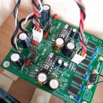
Here an op1611... I have not tried short smd yet here. But The adaptator is directly coupled to the pcb to try to reduce the distance to ground...just put some old red ceramic as I have not mkp left...anyway the traces are a bit away from the oap but I can not hear any harchness...maybe it does not oscillate but I have no scope... Further I will try opa1656 on a dual to single dip 8 adaptator and will report if I detect a problem with ears if the op is interested....
Smd is hard in those adaptators hence my questions...about 3D decoupling.
I just replaced the mylar caps on a a board with MKPs...the MKPs being much fatter I had to extend the legs to make everything fit....now I'm scared it's not going to work 🙁 . I'll find out in a few days 😀
It still works with an opa1656.
No problem with a mkp if 5 mm pitch leads. After the load are certainly a concern also about oscillation. In my setup the next stage is a 47k input preamp. Output pin of the oap either opa1656 or op1611 is 100R serie resistor.
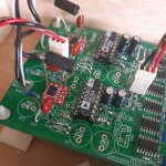
Anyway if it iscillates I can not detect with ears and the soic body doesn't get hot. In my setup a lytic mirror the 0.1 uF at the bottom of the pcb. According Ti pdf it liwisch the stray inductance to the ground, gnd loop shorter as stray inductance. Lead close on the pwr pin and short like if it was a smd...So 3D is possibke with radial mkp. Althougj here in this layout it seems not necessary (AD1862 pcb from Miro1360 member. 4 layers)
Here the long resistor you see are just for test. I/V resistor in rhe oap feedback voltage loop
No problem with a mkp if 5 mm pitch leads. After the load are certainly a concern also about oscillation. In my setup the next stage is a 47k input preamp. Output pin of the oap either opa1656 or op1611 is 100R serie resistor.
Anyway if it iscillates I can not detect with ears and the soic body doesn't get hot. In my setup a lytic mirror the 0.1 uF at the bottom of the pcb. According Ti pdf it liwisch the stray inductance to the ground, gnd loop shorter as stray inductance. Lead close on the pwr pin and short like if it was a smd...So 3D is possibke with radial mkp. Althougj here in this layout it seems not necessary (AD1862 pcb from Miro1360 member. 4 layers)
Here the long resistor you see are just for test. I/V resistor in rhe oap feedback voltage loop
Attachments
If oscillation frequency is very high , megahertz range ,try to add small capacitor from output to inverting input ,like 10pf and more , solder almost directly on pins , and see if it has effect. Fast circuits oscillate when feedback signal is delayed , so some cap will cure that ,it get response from output instant . Long tracks from input pins can also cause catch of noise from nearby devices with smps .
