And let's see how the actual performance is with what you've got. Your junction temps are around 90°C so no worries as long as the mosfets stay attached to the sinks.
And let's see how the actual performance is with what you've got. Your junction temps are around 90°C so no worries as long as the mosfets stay attached to the sinks.
Yes We'll see after my evening tests 😉
trivia who
The G-man ones of course.
(btw, does this look like brown-70 to you ? : http://www.hifine.nl/A-65/content/images/large/a_65_mcs.jpg )
Hi folks!
After being quite busy with work these days, I'm back on the bench🙂
I have replaced the erroneous 10K res on R2 and R15 with 100K ones.
I tightened the fets even more to the sink, then started a new test session.
1h burning time before measurements
R13 = 47.5K
Ambient temp: 21°C
VOLTAGES:
R39 = 266.2mV
R40 = 263.5mV
V- to -G = 4.33V
DC Offset = 21.5mV
TEMPS:
Sink temps:
-Top left = 50.3°C
-Top center = 51.3°C
-Top right = 50.2°C
-Bottom left = 50.3°C
-Bottom center = 50.6°C
-Bottom right = 50.3°C
-Center = 51.4°C
Fets and surrounding sink temps:
-Fet1 = 71°C Sink = 59°C
-Fet2 = 67°C Sink = 58.8°C
-Fet3 = 66°C Sink = 56°C
-Fet4 = 72°C Sink = 57.5°C
-Fet5 = 73°C Sink = 58.1°C
-Fet6 = 72°C Sink = 57°C
Those seems quite correct right? , nonetheless I tightened again Fet 1, 4, 5 and 6
Well, I tried to test the amp, so I assembled my back plane to the sink, the sink to the bottom plate, wiring everything (mainly input and Hp outputs), then bam! fuse blowed......
It take some measures and find that there's some "temporary" continuity between V- (and subsquently source resistor and Fets collector) and ground, the continuity dissappear after few seconds, It has happened as soon as I connected Hp posts to the amp card
What's going on
PS doesn't blow when sink connected to main ground (via chassis), when positive RCA input is connected (not tested with both positive and ground rca alone)
So to sum it up, fuse blow a soon as I connect Hp output (It blowed with positive connected, gnd disconnected) , hp socket are isolated from chassis.
Last edited:
ya mean - haut parleur ?

clarify :
"as I connect Hp output (It blowed with positive connected, gnd disconnected)"
connect to what ?
clarify :
"as I connect Hp output (It blowed with positive connected, gnd disconnected)"
connect to what ?
Yes excuse me, I mean Speaker outputs.
Well, as soon as I connect one of the two speaker posts to the amp then fire up the amp, the fuse blows. I don't understand why, since this shall not make any difference. The only other thing that changes is that the sink on witch the amp is mounted is now in contact with the chassis on witch is connected the safety ground.
I'm quite lost here
PS: my fuse is a temporized 3.15A
Ok, I think I found the culprit, in fact, one of my speaker protection board was shorted to ground (witch cause the 30va trafo to be shorted to ground too) because one of the metal nuts witch retain the board has slitly scratched the pcb surface..... I removed all metal screws/spacers/nuts for the speaker boards and replaced them with nylon ones.
Now there no continuity between the speaker board and the enclosure.
I can't test if it solved the problem since I don't have any 3.15A fuses left (I only got some 2.5A, 6A left).
Now there no continuity between the speaker board and the enclosure.
I can't test if it solved the problem since I don't have any 3.15A fuses left (I only got some 2.5A, 6A left).
That was the culprit!!! 😀 I found another 3.15A laying somewhere on my mess and tada!!!! everything starts (with all input / output connected) Yeah!
I'll post a photo tomorrow to show what the problem was.
I'll try the amp tomorrow as it's quite late now (4am)
Good evening to you and thanks a lot to everyone, you all rocks!
EDIT: I could not wait to test the beast and......IT SINGS!!!!!!!! 😀😀
😀😀
Incredible, even with only one channel and at low volume....can't wait to build the second board😱
I'll post a photo tomorrow to show what the problem was.
I'll try the amp tomorrow as it's quite late now (4am)
Good evening to you and thanks a lot to everyone, you all rocks!
EDIT: I could not wait to test the beast and......IT SINGS!!!!!!!!
😀😀Incredible, even with only one channel and at low volume....can't wait to build the second board😱
Last edited:
A photo of the fuse blower
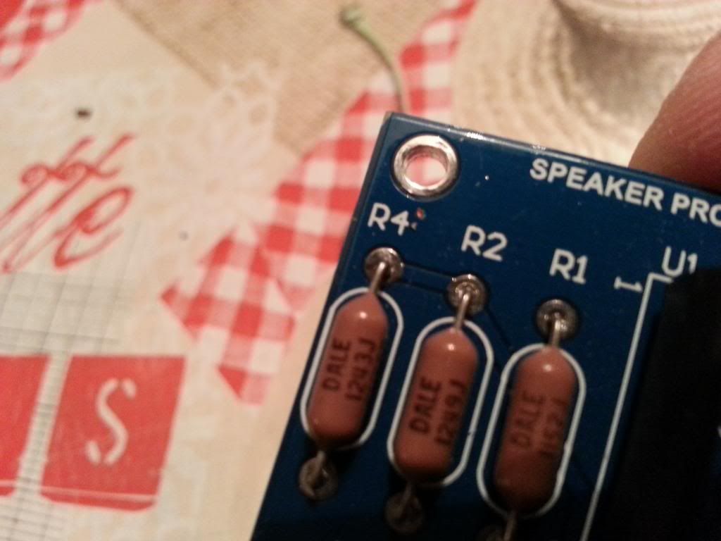
Notice the little scratch next to R4, the nut was making contact with it (in fact, the real culprit was the nut itself witch has scratched the pcb surface) and grounded the 15V ---> not good

Notice the little scratch next to R4, the nut was making contact with it (in fact, the real culprit was the nut itself witch has scratched the pcb surface) and grounded the 15V ---> not good
😛
Never without my multimeter 😀
Zen, a little question, how would you advise me to deal with my input and output signal wire, shall I twist them?
Never without my multimeter 😀
Zen, a little question, how would you advise me to deal with my input and output signal wire, shall I twist them?
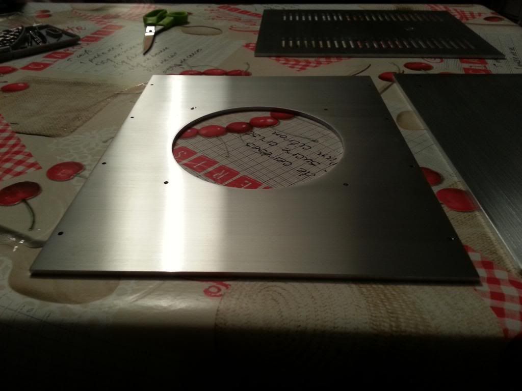
Here some picture of the laser cut aluminum plates I received last week and the before/after sanding process.
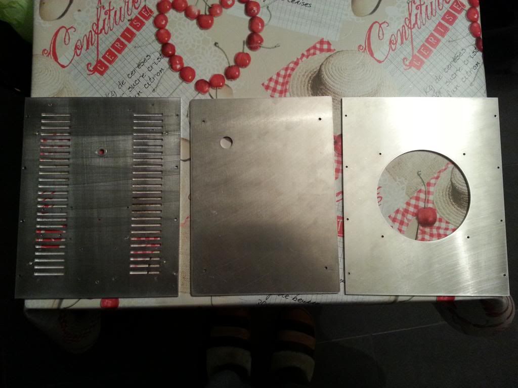
It misses the back plate witch was treated first as I needed it quickly to start the test process. Notice the scratched raw aluminum.......ugly.
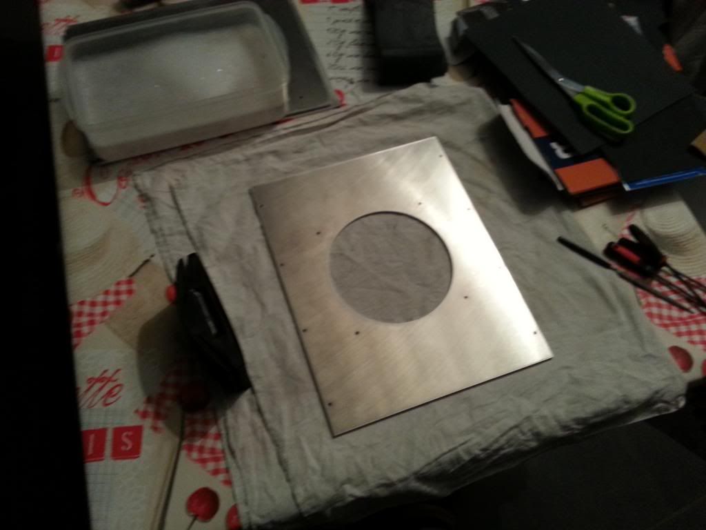
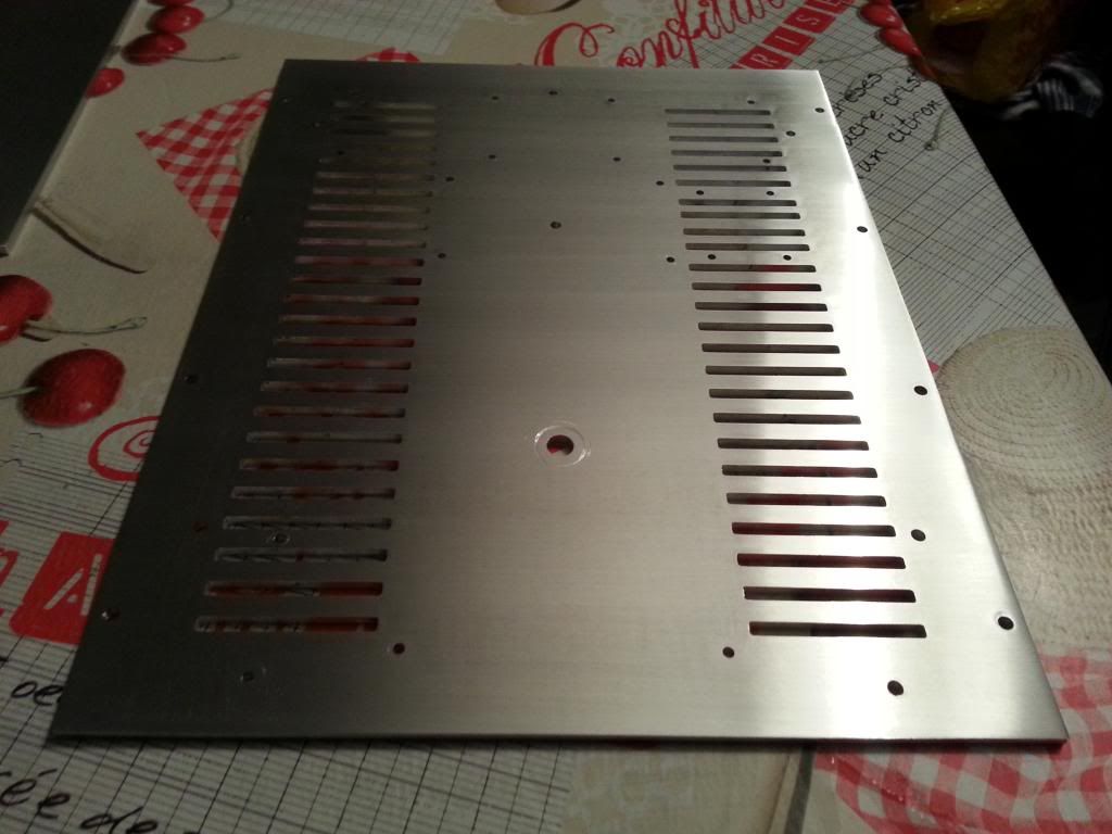
(I know, this one's quite blurry😱) Use a sand block with 280 then 500 fin grain sanding paper (the black ones for metal), use it with warm soapy water (some dish washer should do the trick quite well) and process slowly always in the same direction.
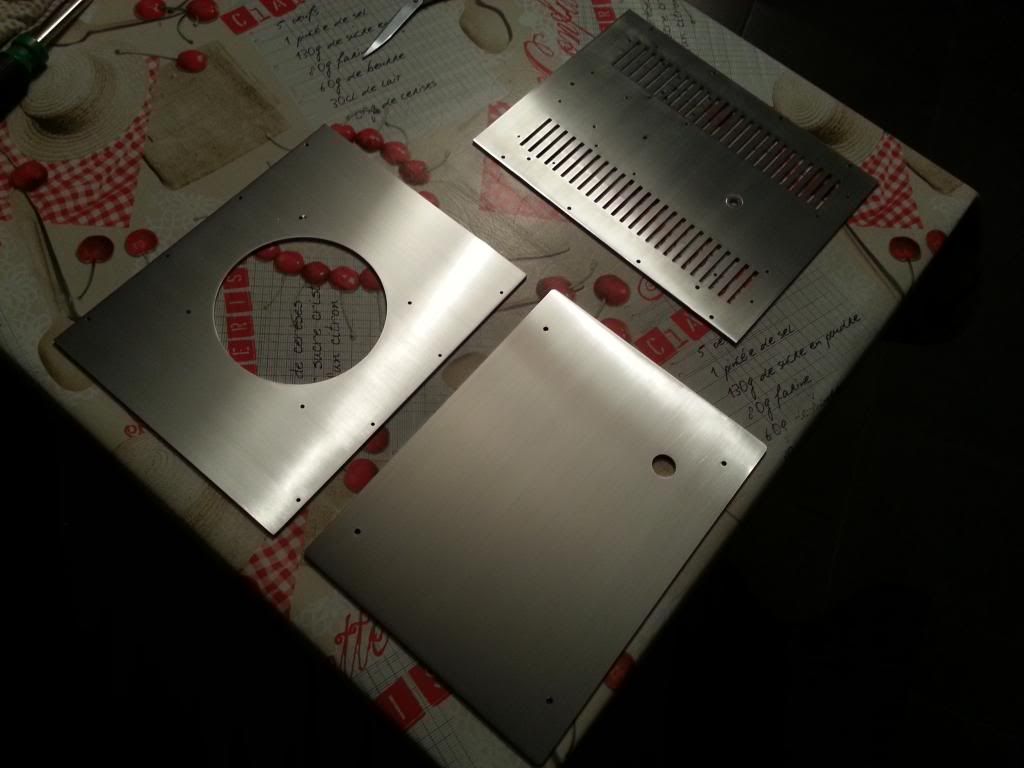
And that's what you will obtain........shiny
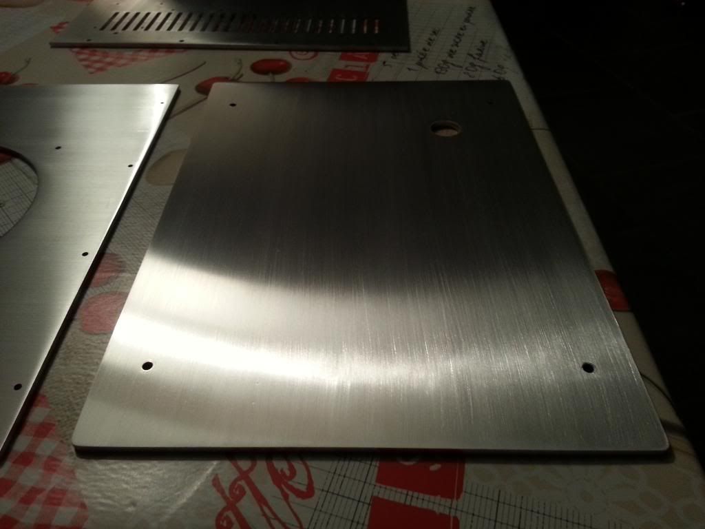
The front plate is not perfect but i think I'l sand it finer (like 800 to 1500) to give it a fine frosted finish.
I think I'll try to find some varnish to coat the finish, a satin one as I don't want the finish to be to shiny or too dull.
The little company that made the cuts have done a great Job, the plates are perfect, done from my own DXF files. For all the french DIYers that wanders here, take a look at John Steel – Dcoupe acier aluminium et inox sur mesure - John Steel and do not hesitate to contact them directly for special cuts, they are very friendly and worships mustaches 😉

It misses the back plate witch was treated first as I needed it quickly to start the test process. Notice the scratched raw aluminum.......ugly.

(I know, this one's quite blurry😱) Use a sand block with 280 then 500 fin grain sanding paper (the black ones for metal), use it with warm soapy water (some dish washer should do the trick quite well) and process slowly always in the same direction.

And that's what you will obtain........shiny


The front plate is not perfect but i think I'l sand it finer (like 800 to 1500) to give it a fine frosted finish.
I think I'll try to find some varnish to coat the finish, a satin one as I don't want the finish to be to shiny or too dull.
The little company that made the cuts have done a great Job, the plates are perfect, done from my own DXF files. For all the french DIYers that wanders here, take a look at John Steel – Dcoupe acier aluminium et inox sur mesure - John Steel and do not hesitate to contact them directly for special cuts, they are very friendly and worships mustaches 😉
- Status
- Not open for further replies.
- Home
- Amplifiers
- Pass Labs
- Beginner to build an Aleph30 needs some help