I put together this little class A amp yesterday and fired it up. It sounds really good, (left out the bass boost R5, C5). I thought this would be a good project to get my feet wet with solid state amps. I have a couple of questions though,
1. The total current draw should be 700mA. The notes that came with the schematic say:
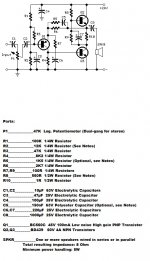
"Total current drawing of the circuit, best measured by inserting the probes of an Avo-meter across the positive output of the power supply and the positive rail input of the amplifier, must be 700mA. Adjust R8 to obtain this value if necessary."
I guess I don't get that. Isn't the positive rail of the power supply and the positive rail input to the amp the same thing? Or are they referring to the plus side of C2.
2. I used 2N3055's instead of the BD439's. Will that require a different total current draw adjustment?
Just that it worked the first time I turned it on was great. Now I have a lot more to learn. I didn't see a "beginner" section to the forum so I posted this here. Please move it if needed.
Link to amp. 3 - 5 Watt Class-A Audio Amplifier - RED - Page80
Tom
1. The total current draw should be 700mA. The notes that came with the schematic say:
"Total current drawing of the circuit, best measured by inserting the probes of an Avo-meter across the positive output of the power supply and the positive rail input of the amplifier, must be 700mA. Adjust R8 to obtain this value if necessary."
I guess I don't get that. Isn't the positive rail of the power supply and the positive rail input to the amp the same thing? Or are they referring to the plus side of C2.
2. I used 2N3055's instead of the BD439's. Will that require a different total current draw adjustment?
Just that it worked the first time I turned it on was great. Now I have a lot more to learn. I didn't see a "beginner" section to the forum so I posted this here. Please move it if needed.
Link to amp. 3 - 5 Watt Class-A Audio Amplifier - RED - Page80
Tom
Attachments
Well, if you perfboarded this you are not that big of a beginner i think.. I'm a beginner too than;-)
You can only measure current with a multimeter if you insert the meter into the circuit. The meter needs to act as a wire between the +output and the +rail input; this way the current flows thru your meter. So yes it's the same thing, voltage is the same.
The reason they say to do it like that is most likely because you have a wire between those 2 point that you can disconnect and get you meter in between.
Hope this helps as a quick fix, think the guru's around here can answer the second one.
I put together this little class A amp yesterday and fired it up. It sounds really good, (left out the bass boost R5, C5). I thought this would be a good project to get my feet wet with solid state amps. I have a couple of questions though,
1. The total current draw should be 700mA. The notes that came with the schematic say:
"Total current drawing of the circuit, best measured by inserting the probes of an Avo-meter across the positive output of the power supply and the positive rail input of the amplifier, must be 700mA. Adjust R8 to obtain this value if necessary."
I guess I don't get that. Isn't the positive rail of the power supply and the positive rail input to the amp the same thing? Or are they referring to the plus side of C2.
2. I used 2N3055's instead of the BD439's. Will that require a different total current draw adjustment?
Just that it worked the first time I turned it on was great. Now I have a lot more to learn. I didn't see a "beginner" section to the forum so I posted this here. Please move it if needed.
Tom
1) The positive rail is the positive arm of C4, or the collector of the output upper transistor.
2) The current may be different with different transistor, because they have different hFE (Or forward static current gain), and being the base current the same, the collector current will be more as the more high is the hFE of the transistors. Perhaps, if the transistor you choose has very low hFE, you must recalculate the base resistors.
Good luck.
A simple way to measure the current is to measure the Voltage across resistor R10. Using Ohm's law you will find that 0.7V divided by 1.0 ohms equals 700 mA. So expect the voltage across R10 to be 0.7V or 700 mV and adjust R8 to a higher resistance if the current is too high.
Well, if you perfboarded this you are not that big of a beginner i think.. I'm a beginner too than;-)
I have built a few things, little power supplies, a couple of tube projects, etc... But they were all based on well documented projects. I want to get to a point where I can build something with parts I may already have such as opamps, mosfets, jfets, power transistors and so on. Just to be able to take some of these parts and understand how they work together, how to power them properly, quiescent current, (biasing), ips,vas, output stages, it just seems like I have so much to learn. Oh well, this little amp is the start. Thanks for the help.
Tom
R2 will probably have to be adjusted to get the output voltage in the correct range. The fact that it is such a low value to begin with tells me that the design is highly dependant on the Beta of the transistors used.
Loudthud, thanks for the help. The design notes say to adjust R2 to obtain 13V across C8. I'll do that and check the current draw per your recommendation. Again, thanks.R2 will probably have to be adjusted to get the output voltage in the correct range. The fact that it is such a low value to begin with tells me that the design is highly dependant on the Beta of the transistors used.
Hi,
Its really not very complicated. You want the output at Q2 emitter to
be at ~ 13V for symmetrical clipping. If its way off adjust R2. As said
earlier the voltage across R10 shoud be ~ 0.7V, way off adjust R8.
The point of C1 is quite lost on me, doesn't make any sense, omit.
rgds, sreten.
Its really not very complicated. You want the output at Q2 emitter to
be at ~ 13V for symmetrical clipping. If its way off adjust R2. As said
earlier the voltage across R10 shoud be ~ 0.7V, way off adjust R8.
The point of C1 is quite lost on me, doesn't make any sense, omit.
rgds, sreten.
Hi,
Its really not very complicated. You want the output at Q2 emitter to
be at ~ 13V for symmetrical clipping. If its way off adjust R2. As said
earlier the voltage across R10 shoud be ~ 0.7V, way off adjust R8.
The point of C1 is quite lost on me, doesn't make any sense, omit.
rgds, sreten.
Thanks sreten, I adjusted R2 to get ~13V at Q2 emitter which then dropped the voltage across R10 to around 550mA. I just need to find the right balance between R2 and R8. Also removed C1. I also tried the bass boost circuit. Didn't like it. Seems to dark to me. Thanks
Tom
Begineer question current draw phase II
Ok, Like I said, I built this little amp, actually breadboarded it, tweaked the values of R2 and R8 to get ~13V on R2 and ~700mA current draw. Sounded good. Then I perboarded it. Double checked all connections, solder joints etc... Fired it up and checked R2. Now around 7-8V and 1.2A current draw. I applied input and it didn't sound bad but definitely not as good. I figured it would change a little, but that seems like a lot. Question is, is that pretty typical. To change that much between breadboard and perfboard? I even checked resistor values before I soldered them on.
Tom
Once you have played with this and understand what is happening.
Strong hint:
Measure the volts drop across every resistor.
Calculate the current through every resistor.
Mark on the schematic the current flowing through every resistor.
Mark on the schematic all the operating voltages.
Green, red, blue and black pens help.
Now build a jlh.
Strong hint:
Measure the volts drop across every resistor.
Calculate the current through every resistor.
Mark on the schematic the current flowing through every resistor.
Mark on the schematic all the operating voltages.
Green, red, blue and black pens help.
Now build a jlh.
Now build a jlh.
I have a couple of JLH 2005 boards that will be my next project, but I had all the parts for this build, and it seemed like a good starting point. Thanks for the tips AndrewT. As far as this current build though, should I expect such big changes from breadboard to perfboard? Wanted to add that I was measuring from the positive of C8 to ground for the 13V and measuring across R10 to get current draw.
Tom
Last edited:
- Status
- Not open for further replies.
- Home
- Amplifiers
- Solid State
- Beginner question current draw