When building this as a real-world amplifier, is it not a good idea to have a coupling capacitor and RF filter at the input?
Also, on Rod Elliots lateral Mosfet design (P101), he adds capacitance to the 2SK1058 such that the gate capacitace matches the inherently higher capacitance of the 2SJ162. Is this not a concern with this type of driver?
Is a Zobel required for stability too on this amplifier? Or any kind of miller caps?
I'll build this amp with 2N5551/2N5401 complement and my Exicon 10P16/10N16 and see how it goes. Just need some aluminium angle for those TO3 devices.
A coupling cap is good. Almost required. And RF filter, too.
I just take it for granted and so leave it to put it there.
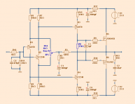
If you see I have different value for Gate stoppers. 330 and 220.
Zobel. Yes, of course.
And you see it on my latest schematics.
Like it a lot, Lineup! Have you built it too?
How about adding cascodes to the input transistors?
The base of a cascode for U1 could be connected to the emitter of U2 (perhaps with a diode (LED or zener) between U1/U2 emitter and R1/R6 for more voltage across the input transistors) and vice versa.
Thanks.
No. I dont build amplifiers. I have not the possibility.
I just provide ideas.
I will explore cascoding and see what it gives.
Did not think of this.hehe.....why not put the zetex to 92 mosfets into this circuit as well...??
But now that you mention it 🙂
Hi Lineup. Looks good.
R14 will limit the slewrate. even if it is CFB you need a lowimpedance that feedback need to look into.
R14 trimmer is a weak spot.Try adjust the bias current and look at signal on centertap of r14.
You would proberly see the crossover distortion as soon as you go below 350mA.
But anyway it looks nice.
The two arms of R14 decide the current. 0.65/500 Ohm = 1.3mA
It would be possible to use one 500 Ohm trimmer.
mikelm did a tryout of different currents.
Bias current of 300 mA was ideal.
R14 trimmer is a weak spot.
The two arms of R14 decide the current. 0.65/500 Ohm = 1.3mA
It would be possible to use one 500 Ohm trimmer.
mikelm did a tryout of different currents.
Bias current of 300 mA was ideal.
Ok, i only mention it because of the other amp i have made that is simelar if topology to this one. I can clearly see the crossover region at "in-".
But if 300mA is the optimum, then this is as it should be.
300 or 350mA probably depends a bit on which Laterals.
Anyway I leave it to anyone building to adjust the bias.
Anyway I leave it to anyone building to adjust the bias.
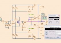
The latest version.
Uses KSA1881/KSC3503 as VAS.
Which gives as low THD distortion as 0.001%
.
At 1W ? Most will do that ! If you simulate a amp at 200+w (below) , and it does .001% , then you could be assured it just MIGHT do this at the "first watt". In short , if it can retain it's linearity at close to full "swing" (rail to rail) , it would have no problem doing so at 1W. As we all know , the low distortion will not ensure a good sounding amp. PIM , THD structure and how the OP interacts with the load will determine that. Sometimes you will luck out , changing real components on the real thing to get it just right. 🙂
OS
Attachments
Ostripper
Thanks for your comment.
With a complicated multi transistor amp with error correction you get such figures rail to rail
I am sure you have bothered do such amplifiers 😉
Considering the simplicity THD 0.001% is good in my amplifier.
I would even say very good.
And you know it.
Have you any suggestion how I may improve further here?
10-12 devices is complicated ? In simulation one can even get the input pair itself down to .03-04% in isolation. A typical 10-12 device IPS/VAS actually just has 4-6 true active devices. Cascodes and current sources just act as support for the important players (devices). Believe me , I don't discount low device count circuits nor do I support the 20-30 transistor "diy-over-engineered" mental masturbation creations. Good work - I do build 4 transistor circuits (after I have added a few more 😀)
PS- that above was with a simple 8 device IPS/VAS (NO error correction-just a little NFB)
OS
PS- that above was with a simple 8 device IPS/VAS (NO error correction-just a little NFB)
OS
I believe the key to a good sounding amplifier is that it keeps the distortion profile throughout the power range...I believe the listener will persive such an amplifier as effortless and powerful...A criteria must also be Hugh (AKSA) rule of thumb that 98% of the distortion should have low order (1-4th) origin.
I have also need for a more Powerful Amplifier than the J-fet-Amplifier can offer with the suggested Rails...so I must look at other devices and operate them with the use of cascodes...But it's entirely possible also with simple circuits to reach good results...But like O-stripper says you may have to use some more support devices..
I have also need for a more Powerful Amplifier than the J-fet-Amplifier can offer with the suggested Rails...so I must look at other devices and operate them with the use of cascodes...But it's entirely possible also with simple circuits to reach good results...But like O-stripper says you may have to use some more support devices..
The latest version.
Uses KSA1881/KSC3503 as VAS.
Which gives as low THD distortion as 0.001%
.
Hi Lineup,
Can you please provide a scaled-up version with supply rails like 42V?
I think that KSA1381/KSC3503 & one pair of J162/K1058 can handle that kind of power.
Cheers, Stanley
- Status
- Not open for further replies.
- Home
- Amplifiers
- Solid State
- BC550-560 Symmetric with LATERAL Output - Hiraga style