Is it possible to build a practical Baxandall type passive tone control for a fully differential topology? What I am looking at is input transformer phase splitter with balanced circuitry all the way to the OPT. So would have input transformer - shunt volume control - balanced gain stage - tone stck - balanced drivers etc.
Putting a simple shunt treble cut is easy but for the more complex bass&treble boost/cut it is trickier. Putting a standard Baxandall in each phase using twin pots seems like an invitation to imbalance problems. Putting the standard circuit across the two phases (bottom phase connected where ground is normally connected) seems to jack up the next amplification stage. I suppose this is due to some unbalanced impedance.
So is it possible/practical to make such a thing.
I think the quick answer is no. If you put Baxandall (or any other) tone controls in both phases with twin pots then you won't get exactly the same amplitude and phase shift changes in both phases, although with well-matched pots it might not be too bad.
To put one Baxandall between the phases won't work because it assumes a ground reference. You need to find a tone control topology which doesn't use a ground reference, so you are processing the combined signal rather than each phase separately. You may be able to take an existing passive circuit and modify it, but remember that passive tone control attenuates the signal so you may need an extra stage of amplification.
To put one Baxandall between the phases won't work because it assumes a ground reference. You need to find a tone control topology which doesn't use a ground reference, so you are processing the combined signal rather than each phase separately. You may be able to take an existing passive circuit and modify it, but remember that passive tone control attenuates the signal so you may need an extra stage of amplification.
Thanks DF. That is kind of what I was thinking. One idea I came up with is to put in a fixed series RCL shunt across the phases and then use a normal RC shunt treble control and RL shunt bass control in parallel. I think this would work but the inductors would need to be rather large I fear.
I once designed a mixer that should be cheap, and have Baxandall type controls in each channel. I did high and low shelf attenuation only in channel strips, and made shelf boosts for tops and lows in a summing amp. It worked exactly like Baxandall, but sounded amazingly nice on lows, may be because I used a real inductance there.
May be something similar can be used in your case?
Edit: yesterday I replaced an active 40 Hz LPF on subwoofer channel by a 2-nd order LRC one. What an improvement!
May be something similar can be used in your case?
Edit: yesterday I replaced an active 40 Hz LPF on subwoofer channel by a 2-nd order LRC one. What an improvement!
Last edited:
I am not sure I follow what you are describing Wavebourn. Are you saying that you did passive cut only filters in each channel and then added the ability to boost later after the channels were combined?
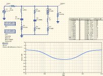
Here is what I was trying to describe earlier. In this case I simulated a single ended version but I think the same type of thing could be cone across the phases of a differential system.

R4 and R6 are 25k variable resistors in this case.
Here is what I was trying to describe earlier. In this case I simulated a single ended version but I think the same type of thing could be cone across the phases of a differential system.
R4 and R6 are 25k variable resistors in this case.
Attachments
I am not sure I follow what you are describing Wavebourn. Are you saying that you did passive cut only filters in each channel and then added the ability to boost later after the channels were combined?
Highs and lows were boosted constantly. I added ability to cut in each channel. Similarly, you can use such cuts and boosts between symmetrical wires.
Here is a sketch I drew for you, to show the concept:
Attachments
As a practical matter I have been unable to get the three branch shunt system above to work well due to interactions between the branches. I had an idea last night so I ran some back of the napkin calculations and I think I have a workable plan.
My initial plan had been to use the output to the subwoofer amp as the bass control and then use the simple shunt treble cut which simulates quite nicely. It hit me that a partially bypassed Rk on the input stage would, with a sufficiently small capacitor give me a few dB of treble boost. I could then use the shunt treble cut to make it flat in the middle of the pot travel giving a fully functional treble control to go with the bass control.
Initial simulations look promising. I ran a quick run before supper and was able to get 4 or 5dB with a pretty flat bass and midrange rather easily. It looked good using separate bias for each input tube but for some reason my simulations failed when I tried using a single bias network for both tubes. I figure I must have inadvertently screwed up some connection on the schematic as in theory it should work either way. It would be advantageous to use a single bias network so that there are fewer variables in the two phases. You will still have the issue of differing gm on the two tubes but that is the case in any PP circuit.
Looks like this is worth pursuing to me.
To summarize the current design is an input transformer/phase splitter driving a shunt volume control with a high Z jFET subwoofer EQ circuit tapping off of one phase. The PP signal from the volume control is fed to a differential voltage amp stage using low to medium mu triodes (current sim is 6N1P but any number of possible suspects could be used here) with partial bypass Rk to provide treble boost.
The output of the first VAS is fed to the Schade style driver/output stage with a shunt treble cut coordinated to provide an overall boost and cut of about +/- 4 or 5 dB. The drivers are cathode biased 12AT7s with no bypass on Rk. The coupling capacitors to the output 6BQ5s are sized to provide HP filtering at the crossover point of the subwoofer. The crossover point "happens" to coincide with the natural roll off of the main speakers making higher order crossover unnecessary. I plan on UL output but pentode mode is also a possible option. I am currently simulating with resistive cathode bias with bypass on the output tubes but I am considering LED ala SY as a possible option.
Realized as I was drifting off to sleep that the gain with total bypass is not that much greater than with none so I don't need to split the cathode resistance, just bypass it all with a sufficiently small cap. Duh. 🙂 No time tonight but will play around more on Wednesday.
how did you go with this? I need to add a bass control to the input of a balanced headphone amp. well to be precise i'm adding a balanced headamp to the output of a sabre dac i'm building for a mate, the amp PCB has an onboard pic controlled relay based attenuator, but i'm not populating this as i'm using the digital volume control of the sabre, so I thought of modifying the attenuator to become the bass control. the amp is a fully differential opamp input (THS4031) with lateral mosfet output drivers and the relay volume is active within the THS4031 feedback. seems to me it should be possible but not quite sure how to approach it in a balanced topology.
any ideas guys??
any ideas guys??
I haven't committed anything to solder yet, but I have pretty much decided to use a SE front end and put the treble control there before the phase splitter. I had been hoping to save on heat and space by running the sources directly into the splitter but it just doesn't seem worth the effort in my situation. I may be wrong on that point of course.
Qusp, are you saying that your DAC has a differential output or that you are going into a differential amp? If the latter you could take the output of the DAC into say a jFET stage and implement a simple boost cut control there before going into the differential amp. If you have to go differential the difficulty would seem to be getting a perfectly symmetrical boost on each leg. In my simulation the shunt cut seemed to work pretty well as long as there was only a single band (e.g. only treble). For me I had the luxury of defining my own topology.
Qusp, are you saying that your DAC has a differential output or that you are going into a differential amp? If the latter you could take the output of the DAC into say a jFET stage and implement a simple boost cut control there before going into the differential amp. If you have to go differential the difficulty would seem to be getting a perfectly symmetrical boost on each leg. In my simulation the shunt cut seemed to work pretty well as long as there was only a single band (e.g. only treble). For me I had the luxury of defining my own topology.
out of a balanced sabre dac and into a balanced headphone amp. the headphone amp has a relay based volume control at the input that exists in the feedback loop of a diff opamp, so was wondering, since Idont need the volume, as im using the digital volume of thye sabre dac via MCU, whether I could bend this volume control to the task of an active filter bass boost. by installing a small 0.22uf (or there abouts) film cap across the rails at the input and resistors for a number (not al, dont need that many levels) of the relay positions. basically populating the volume control, but in a slightly different manner.
here is the amp schematic. uses a pic to control the volume circuit. its basically a modified AMB M3 with relay attenuator onboard, turned to fully differential operation, rather than the brute force dual mono type 'balanced' implementation of just building 2 amps. uses more SMD components, has modified CCS and has an onboard jung type regulated power supply. so its a nice space saver when compared to building 2 amps and not populating the ground channels, then adding a sigma11 power supply, that just takes up too much room and puts out too much heat for my purposes, ie and all in one dac/IV/Headphone amp
I also considered doing it with a low noise dual JFET like the linear systems LSK389 or similar, but I thought since the volume control is there, would be nice to make use of it
thanks for the reply
Dang that's complicated. If I am following it correctly it looks like the volume control just shunts part of the input signal and the FB is kept constant. In theory it seems like you could make both the shunt and the feedback frequency dependent with shelving treble cut in the feedback and making the shunt effective in the bass region. As long as the components in the feedback loops were very well matched it might just work. Interesting. I will watch with interest.
Its easy to run tone controls with differential operation.
The simple way is to duplicate the tone stack of a single ended circuit for each half of the differential amplifier but using dual controls and the like. However, if you study the resulting circuit, two things should become apparent:
1) you don't need the ground circuits anymore
2) because of that, you can put certain values in series, for example if your tone stack has 2 250pf caps in it, you can put them in series for 125pf.
If you do it right, the resulting differential tone circuit will be floating and you may not even need to use dual controls.
I use a similar technique for phono EQ in the differential domain and it works like a charm.
- Status
- Not open for further replies.
- Home
- Amplifiers
- Tubes / Valves
- baxandall type tone control for diff amp