Never simulated a potentiometer...not as knowledgeable with simulations as you are, so i just did spot simulations .Thank you!
Last edited:

Please don't use the historically illiterate term 'James-Baxandall tone control'. This nomenclature was invented by an EE undergrad for a thesis. There is the James circuit of late 1940s and the Baxandall circuit of 1952. They are not the same, and they are not joint work.
I'm sorry about that...I still don't really know the name of these circuits because they don't look exactly like James, nor like Baxandall as many incarnations have a gain too while looking like a passive network.Besides, they are heavily found in all sort of high-endish equipment so i wouldn't dare to say they are low quality or funcky either, maybe not user friendly is the better term.
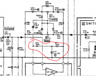
Until then i still need to know the answer for why is that T filter placed there in some commercial versions.
I simm'd the AIWA circuit and with that 150k-22u-150kohm T filter in circuit the phase responseup to 1khz gets worse compared with no filter like that at all.So what is its purpose?
Until then i still need to know the answer for why is that T filter placed there in some commercial versions.
I simm'd the AIWA circuit and with that 150k-22u-150kohm T filter in circuit the phase responseup to 1khz gets worse compared with no filter like that at all.So what is its purpose?
Passive tone control
https://i1.wp.com/admarkelov.ru/wp-...той-регулятор-тембра.gif?resize=300,225&ssl=1
https://i1.wp.com/admarkelov.ru/wp-...той-регулятор-тембра.gif?resize=300,225&ssl=1
I owe you a million dollars Sir but i don't have it 🙂Kenwood Turnkey Solution
Kenwood KR-5030 bias problem help
Prompting me to that kenwood design made me look again in the kenwood l-02 service manual which led me not only to this wonderful page we need the Kensonic-Accuphase designers to thank for:
https://www.diyaudio.com/forums/sol...io-amplifiers-service-manual.html#post6310791
but also to another 2 simplified designs of Kenwood L-02a , the Kenwood KA-9X and 7X which have the tone stack embedded in the feedback loop.The KA- 9X tone stack is resembling the KA-1000 and simulating all of them i found something interesting that i didn't think of before.
While the marantz pm62 with the antilog pots half way gave me the most linear response line although its reviews are kinda bad ones , all the kenwoods, some aiwa and some denon with stellar reviews had a specific and very interesting drop of about 2...3db at 1...2khz with the same antilog pots half way.The only one that i didn't simulated was the KR 5030 cause i can't find 5k antilog pots and build it into something real . I have a feeling that this is one key not just for a good sounding amplifier because in that region the human hearing is very good anyway , but also because in that region you need to measure the most linear response too and make it public 😉
Last edited:
Sometimes it is useful to play with time constants (inflection frequencies) of the timbre block.
Taking into account the peculiarities of acoustics and individual preferences.
In feedback, it is advisable to deliberately limit the depth of adjustment for reasons of stability and overload capacity.
Taking into account the peculiarities of acoustics and individual preferences.
In feedback, it is advisable to deliberately limit the depth of adjustment for reasons of stability and overload capacity.
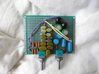
My last choice was to go with the most linear marantz pm62 tone stack although i had to make some minor corrections and apply further compensation to the amp itself as with the pots at the ends i get pronounced peaking. The kenwood amplifiers are 4 times higher speed than the marantz and that is most probably why they preffered that nonlinear response .I didn't sim the kenwood, aiwa and denon tone stack at the end course of the potentiometers though.I think i'll restart the simulations with the kenwood versions although i already built the marantz tone stack...
Attachments
modified them in all ways, but they actually need having a constant gain ratio in both trebble and bass sections..
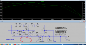
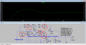
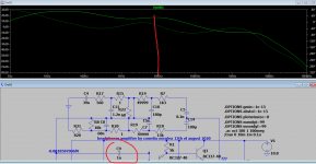
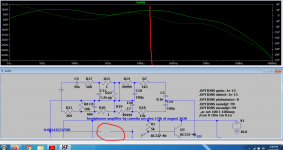
I tried both marantz and kenwood 7X tonestacks with two different gains obtained not externaly, but by modifying the network gain and the results are interesting.
Actually that drop was at around 100...200ohms and it depends on the gain, but what's interesting is that the kenwood doesn't really show an instability but ,with no compensation and with one extreme setting , a greater gain at around 1mhz where you need a lot of feedback, 1nf , to drop it, where marantz barely show any gain, while with the other extreme settings the kenwood behaves better within the audio bandwidth at around 20 ...30khz while marantz screw it at around 80khz and compensating there is actually screwing the global feedback capabilities...So it looks like the marantz tonestack is aimed at a slower amp while the kenwood stack at a naturally higher speed amp.
Actually that drop was at around 100...200ohms and it depends on the gain, but what's interesting is that the kenwood doesn't really show an instability but ,with no compensation and with one extreme setting , a greater gain at around 1mhz where you need a lot of feedback, 1nf , to drop it, where marantz barely show any gain, while with the other extreme settings the kenwood behaves better within the audio bandwidth at around 20 ...30khz while marantz screw it at around 80khz and compensating there is actually screwing the global feedback capabilities...So it looks like the marantz tonestack is aimed at a slower amp while the kenwood stack at a naturally higher speed amp.
Attachments
-
 marantzplot6.png81.8 KB · Views: 61
 -
 marantz plot5.png50.6 KB · Views: 50
 -
 marantz plot4.png49.2 KB · Views: 54
 -
 marantzplot3.png52.6 KB · Views: 55
 -
 marantz plot2.png56.1 KB · Views: 48
 -
 marantz plot1.png57.5 KB · Views: 54
 -
 kenwoodk7xplot4higher gain.png88.9 KB · Views: 70
 -
 kenwoodk7xplot3.png54.5 KB · Views: 73
 -
 kenwoodk7xplot2.png55.7 KB · Views: 83
 -
 kenwoodk7xplot1.png60 KB · Views: 74
Last edited:
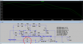

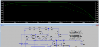
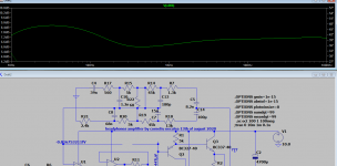
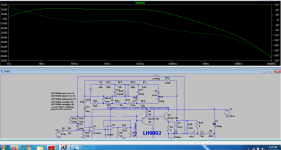
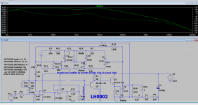
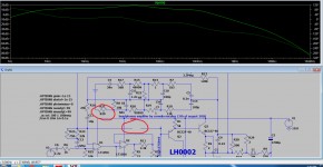
well...of course i didn't use those tone stack the way their designers wanted to...as they applied just a portion of the equalized signal to the real feedback network running in parallel...
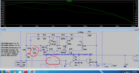
Now here's the interesting part:
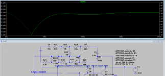
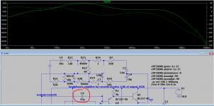
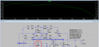
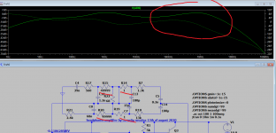
When used as intended by the manufacturer , including the sigma drive circuit on a much weaker amp driving 250 ohms cans with their real impedance there's barely any need for compensation, just 5pf...22pf in one version, but 100pf is safe for everything. and that's also covering my own circuit instability too.There's a drop of 1.5...2db at around 700...1000khz with the pots halfway way, but no other instability when the pots are all the way up or down.I actually forgot to remove the 10k resistor left in there from the marantz tone stack, but removing it the low frequency spectrum is even more linear as you can see in the last picture.
When used as intended by the manufacturer , including the sigma drive circuit on a much weaker amp driving 250 ohms cans with their real impedance there's barely any need for compensation, just 5pf...22pf in one version, but 100pf is safe for everything. and that's also covering my own circuit instability too.There's a drop of 1.5...2db at around 700...1000khz with the pots halfway way, but no other instability when the pots are all the way up or down.I actually forgot to remove the 10k resistor left in there from the marantz tone stack, but removing it the low frequency spectrum is even more linear as you can see in the last picture.
Attachments


Last edited:
- Home
- Amplifiers
- Solid State
- Baxandall active tone stack applied to headphones amplifier?