I am trying to add a battery level monitor to 4 x Li-ion batteries in series to monitor the levels. I found this seemingly simple circuit on an another site & the LED indicators are set at the following voltages.
Above 11.6v..............Green "on"
Between 10.5v -11.6..... Yellow "on"
@ 10.5v..............Red "on"
However, the above settings are a bit low for Li-ions & I need to change these to the following;
Above 11.9v ..... green LED "on" ( 2.975v/battery )
Between 11.9-11.5 ..... Yellow "on" ( 2.975-2.875v/batt )
Below 11.5v.................red "on" ( 2.875v/batt)
Can someone please show me how to calculate the component values to obtain the above levels?
Thanks
Attachments
The thresholds are based on the zener diode ratings.
To change them you have to get different zeners.
Or a more complicated circuit that is adjustable.
Hope that helps
To change them you have to get different zeners.
Or a more complicated circuit that is adjustable.
Hope that helps
Thanks DUG!
I guessed it too! Would you care to explain briefly how these 2 zener values control/change the voltages? What formula or math is needed to do this?
Thanks.
I guessed it too! Would you care to explain briefly how these 2 zener values control/change the voltages? What formula or math is needed to do this?
Thanks.
Such a simple circuit has very imprecise levels and I would doubt you would get it exact enough for a Li-On battery for the results to be useful.
Its easy to work out how it all works. Remember a zener won't conduct until the voltage across it exceeds its marked value. So the 8.2 volt zener does nothing until the supply exceeds 8.2 volts plus the forward voltage of the LED (say 2 volts). So at around 10.2 volts the zener starts to conduct and the LED dimly comes to life getting brighter as the supply increases. So the problems there are a poorly defined operating point and an LED that varies in brightness. The other LED is "lit all the time" via the 1K but relies on a transistor to short out the LED when the other zener begins to conduct at around 11 volts plus the Vbe of the transistor. Again a poorly defined set up and also wasteful of battery power.
I once designed a circuit using a dual bi-colour LED to monitor a car battery. It used a comparator set up as an oscillator and the LED changed gradually from green through yellow and orange to red as the voltage altered.
For Li-On voltage indications I would look at using comparators and a stable reference voltage to set the "trip" points exactly... sadly that becomes a much more complex project. I would also design for "micro power" use too so that current consumption is at a minimum.
I use a variation of this circuit for projects and it is adjustable.
http://kd1jv.qrpradio.com/batmon/batmon.HTM
I'll see if I have the link for the one I use at home. It uses fewer parts and has a zener instead of a regulator for the voltage reference.
http://kd1jv.qrpradio.com/batmon/batmon.HTM
I'll see if I have the link for the one I use at home. It uses fewer parts and has a zener instead of a regulator for the voltage reference.
Thanks Mooly for your timely warning! Li-ion battery charge/discharge voltages are indeed very critical & such need very precise monitoring. So I will try the one Spwalek has linked.
Spwalek, thanks for the link. I do have this schematic & actually wanted to try this,but was a little hesitant due it's rather high current draw. So I wonder if I could substitute either LM2940 or LM1117 LDOs than LM7805 regulator as used in the original circuit?
I have a TA7805S which is supposed to be somewhat better than other xx7805s. Would you guys recommend 7805 reg? Noise is on of my prime concerns other than high current draw!
Could you link your mod to this circuit please?
Thanks
Last edited:
Just found out that the TA7805S has a max input voltage-Vin-of only 10V! This means I can't use this device!
If you don't need constant monitoring, you could easily add a momentary pushbutton to your battery gauge circuit power. This would considerably reduce the needed battery draw.
Hi,
I do not know If you have access to a micro but attached it is an schematic showing how easy it is done using a micro.
The micro program will read the battery voltage input and depending of the different setting in the program it will turn on the led light. Simple and the programming can be done using a Picaxe or a Basic Micro NANO8 micro.
Attachments
As long as the chips are pin compatible I don't think it will matter. I've subbed tl082 and tl072s with no problem. I usually set this up as a power on indicator LED with the voltage monitor as a bonus. I did not see a noticeable power use increase, but I'm using an SLA. You could also set it up with a momentary contact switch on the power lead for an "as needed" check.
Thanks guys,. Sorry I'm completely green on anything "digital",let alone on programing! So it has to be pure analogue for me! but could perhaps incorporate just a non latching switch just to check the voltage from time to time. But would be nicer if not critical to also have a visual indication of the battery status as these are Li-ions!
The schematic i've got seems quite neat & relatively simple. I need only to change to a better LDO like a fixed 5v LM2940. This should be a better choice with low ESR caps on both in & out.
How about TL750L-T092 ?
The schematic i've got seems quite neat & relatively simple. I need only to change to a better LDO like a fixed 5v LM2940. This should be a better choice with low ESR caps on both in & out.
How about TL750L-T092 ?
Attachments
Last edited:
I couldn't find a link with the mods I made to the circuit. After looking at my notes I think I combined 2 different circuits. The attached gif is what I've been using. I don't know what the current draw is but all the components are common.
If your careful with layout it can fit on a 1/2 x 1" veroboard. Without checking I'm not sure on the chip numbers you referenced. I'm pretty confident that any 8 pin dip op amp will work, just check the pinout matches the LM358,TL072 etc.
If your careful with layout it can fit on a 1/2 x 1" veroboard. Without checking I'm not sure on the chip numbers you referenced. I'm pretty confident that any 8 pin dip op amp will work, just check the pinout matches the LM358,TL072 etc.
Attachments
Last edited:
The simplest way to achieve what you want is with an op-amp. A basic quad op-amp with a potential divider on each input.
Spwalek,thank you so much for your modded schematic! Have you used 1/2 trimmers or proper potentiometers? Although I'm running 4 x 2900mA Li-ion batteries in series, my circuit consumes only around 100mA at the most. So, I'd like to try TL750L which has a very small foot print (T092) & has a quiescent current of only 1mA!
Yes, Katie&Dad , I did consider using an op-amp, but found one circuit using an obsolute LM709 chip. I couldn't find any better alternatives either! I then somehow got sidetracked by the above circuit! Do you have any design leads or links i can have a look at? If you do, then could you please direct me to these.
I've narrowed down to 3 LDOs...
LM2940
LM1117
TL750L...which is my favorite a.t.m!
Last edited:
Telemon,
Look at the circuit I posted again. The zener should draw less current than the regulators would. It is just there to provide a voltage reference point for the op-amps. As far as the trimmers they are small 1/8 or 1/4 watt ones from a grab bag I bought. I would recommend bread boarding the circuit both ways and see what draws less current with an ammeter. My only concern with the regulator is the extra parts/cost
Look at the circuit I posted again. The zener should draw less current than the regulators would. It is just there to provide a voltage reference point for the op-amps. As far as the trimmers they are small 1/8 or 1/4 watt ones from a grab bag I bought. I would recommend bread boarding the circuit both ways and see what draws less current with an ammeter. My only concern with the regulator is the extra parts/cost
For "critical" apps (we're still talking diy audio aren't we?) perhaps just a low voltage shutoff circuit would be appropriate. Has this been considered?But would be nicer if not critical to also have a visual indication of the battery status as these are Li-ions!
Yes, but as I mentioned earlier, this circuit will be running on li-ion batteries,which require a little more attention than alkalines or NiCd to the charge/discharge voltages. hence this circuit gives a better visual display warning of the levels.
Here are a few more possible 5v LDO regulators with various quiescent current,Vin/Vout specs;
TA78PL05AP-5v/ Iout=250mA max
LP2954 -5v7 Iout=250mA max
MCP1702- Iout=250mA max
TL750L05-5v Iout=150mA
Here are a few more possible 5v LDO regulators with various quiescent current,Vin/Vout specs;
TA78PL05AP-5v/ Iout=250mA max
LP2954 -5v7 Iout=250mA max
MCP1702- Iout=250mA max
TL750L05-5v Iout=150mA
...or buy proper Voltmeter 😱
3Pcs Mini DC 0V To 99.9V Red LED Digital Panel Volt Voltage Meter Voltmeter -- BuyinCoins.com
or
http://buyincoins.com/item/16263.html
3Pcs Mini DC 0V To 99.9V Red LED Digital Panel Volt Voltage Meter Voltmeter -- BuyinCoins.com
or
http://buyincoins.com/item/16263.html
Last edited:
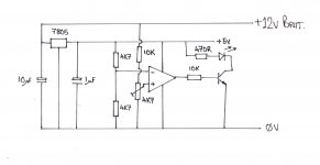
You can use almost any op-amp, even the lowly 741. Run a regular 5V 7805 to give you an op-amp supply.
Then the op-amp can have two potential dividers on its two inputs. Bear in mind that the op-amp will only allow an input up to its Vcc. So the potential dividers can be set to provide say 2.5V at the trigger point. The output of the op-amp can feed the base of an NPN transistor via a 10K resistor to switch on the alarm LED.
This method will be as accurate as your potential divider +/- the threshold voltage of the op-amp which will be mV.
Something like this.
Attachments
Last edited:
- Status
- Not open for further replies.
- Home
- Amplifiers
- Power Supplies
- BATTERY LEVEL MONITOR