That's odd.
The transformer is original.
"SLME" stands for Ampeg (St. Louis Music)
The number matches the Ampeg part number for the export transformer.
There is a transformer without voltage selection, but this one has only 2 primary wires, part number would be 94-015-01
Anyway, 2x53V seems too high, this would rather match a 300W amp.
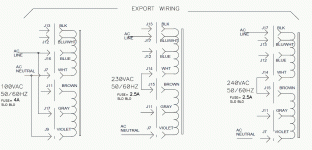
Is this the wiring you did? I see it on the schematic, but it is aimed for 100V:
Blue and grey tied together to J16/17
White and violet tied together to J7/9
The remaining black, brown and blue/white wires are each being parked on one of the "empty" terminals J11/12/13
For 120V it should look like this, but it is not on (my) schematic:
black and brown on J16/17
white and violet on 7/9 (as before)
now blue, blue/white and grey remain unused and again are parked on J11/12/13.
with the transformer still disconnected, you can check the primary resistance between black & white and brown & violet respectively, none of them should be open.
Last edited:
Georg, you have saved the day again. So it turns out the primary was wired correctly after all. My apologies to the amps previous owner for any negative comments I may have said about him or her. When I originally disassembled it, I wrote down all the positions and they matched exactly what you wrote. I have no idea why I could not find that info on my schematic. Anyhow, that reduced the secondary to 44VAC and now my +/- rails are running at 54V. SUCCESS! In case you were worried, I did drop the bias back down before firing the amp up with the primary wired correctly and reset the bias voltage there after. So I think it is official, this amp has been brought back from the dead. Next up I have an SWR workingman 160 I need to work on… just kidding. Thank you so much for your help.
Yes, it looks like you are through, well done!
Glad I could be of help.
Obviously it did not not come to Ampeg's mind that someone in the US would use a model with an export transformer, so the 120V wiring is not noted. When looking at the wiring schematics, you can tell that the primary cosists of two separate 120V windings.
One (the lower one) with a 100V tap, the other one with 100 and 110V taps. For 100 and 120V operation the windings are paralleled using their respective taps.
For 240V the full (untapped) windings would be wired in series.
So, from bottom to top:
0, 100, 120V
0, 100, 110, 120V
Attachments
Last edited:
- Status
- Not open for further replies.
