Hi. I'm building the PSU for my phono stage. IEC input (switched and fused) at the back to switch at the front, from there to the transformer primary.
My question is super-basic. Do I need to carry LIVE and NEUTRAL to the switch (which is dipole and would switch both L and N) ? Or should N go directly to the 0v primary on the TX ?
In short, is it ok to simply interrupt the LIVE with the switch, or should both L & N be interrupted ?
My question is super-basic. Do I need to carry LIVE and NEUTRAL to the switch (which is dipole and would switch both L and N) ? Or should N go directly to the 0v primary on the TX ?
In short, is it ok to simply interrupt the LIVE with the switch, or should both L & N be interrupted ?
A lot of commercial equipment does just switch the live however if go down that route then you must be aware of the risks involved.
If you get the polarity 'wrong' or if you plug the unit into a socket with reversed polarity then the primary side of things becomes live as it is now effectively the neutral that is being switched. In a properly engineered product that is of no consequence as the user should not be able to touch anything on the mains side anyway.
As your switch is double pole I would suggest you switch both live and neutral.
Remember that all wires (with changing current) should be run as close coupled Flow and Returns pairs, Twisted is better.
If after the fuse you run to the switch, then those wires to the fuse are both Live.
The Flow to the fuse should be twisted with the return from the fuse.
Then the fused Live is twisted with the Neutral and that pair goes to the switch
If after the fuse you run to the switch, then those wires to the fuse are both Live.
The Flow to the fuse should be twisted with the return from the fuse.
Then the fused Live is twisted with the Neutral and that pair goes to the switch
Remember that all wires (with changing current) should be run as close coupled Flow and Returns pairs, Twisted is better.
If after the fuse you run to the switch, then those wires to the fuse are both Live.
The Flow to the fuse should be twisted with the return from the fuse.
Then the fused Live is twisted with the Neutral and that pair goes to the switch
Good point - thanks
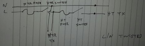
Attached is a hastily drawn sketch of what I intend, from the IEC on the left. Separate transformers for HT and heater supplies.
Intention is that if the first fuse blows, or the heaters are switched off, then the HT supply is cut. I welcome any comments.
The first fuse will need to be sized for heater current (2 x 12AX7 + 2 x 6922 = 1200mA) + HT current (2 x 34mA). Inrush current will be much higher, LTSpice indicates perhaps 350mA during the first 0.2 seconds on HT. I'm not sure what the startup current through the cold heaters will be. Both fuses will be slow-blow, thinking 250mA for HT and 2A for HTR+HT. I also note that some people recommend circuit breakers instead of fuses. Hmmm.
I appreciate that this leaves the risk of someone using an incorrectly wired IEC plug and i'll ponder that one. Though this will only be used by me I might still decide to rethink this.
Attachments
Filaments of bulbs increase their resistance from cold to hot by a factor of around 10 to 12
Halogen bulbs because they run a little hotter will be a slightly higher factor.
The heater does not run as hot, so a factor around 4 to 8 is probably in the ballpark. It would be easy to measure the cold resistance and see what you get.
This is the resistive load on the transformer secondary. The primary current will see this transformed current. This will result in the primary current initially running at 4 to 8 times higher than the fully warmed up current. This is probably a similar factor to the start up current for the transformer. Use the usual 3times primary operating current as the fuse rating and it will probably survive this start up and warm up duty.
What is the heater transformer VA rating?
What is the primary operating current?
What is 3times that?
The heater transformer primary is 0-230V. It has two secondaries, each 9V 25VA, both in use (6922s will have elevated voltage).
The transformer is stepping voltage down by a factor of 27.8 (250/9).
Primary power = 230 x Ip
Secondary power = 2 x (9 x 0.6)
Solving for Ip gives 47mA, unless I've grossly misunderstood something.
3 x 47mA = 150mA ish, so perhaps my 2A guess was a bit high !!!
The specs for the slow-blow fuses seem to indicate that they will fail quickly (sub-second) at around 2.5 times rating. It seems I should be aiming for a rating of around 100mA ? I'm not sure I've seen them that low, but will look around. I have 250mA and will use those if I don't find them.
Andrew thanks for asking the right questions and leading me through that.
I would use a T250mA mains fuse for that tiny transformer.
I probably don't have that in stock, so I would use an F500mA.
It will probably blow at about the same speed as a T250mA at a similar overload current.
If your transformer is rated at 50VA ("each 9V 25VA"), then it is not a 47mAac maximum operating current.
50/230 = 217mA
three times that is 652mA
Use a T800mA, or 1A
1A are available as BS1362 to fit BS1363 plug tops.
Last edited:
I would use a T250mA mains fuse for that tiny transformer.
I probably don't have that in stock, so I would use an F500mA.
It will probably blow at about the same speed as a T250mA at a similar overload current.
Thanks
Andrew (this thread has turned into a transformer tutorial) could I ask you to check my calcs for the HT transformer please ?
primary input is 0-240V
centre-tapped secondary and I'm using B+ and B-, output is 300-0-300. B+ and B- will each draw around 35mA when operating so I make the secondary power 600 x 0.07 = 42VA
42 / 240 = 175mA primary current
allowing a factor of 3 indicates a T500mA fuse would be just under, perhaps this for the second fuse (HT only)...
https://www.edwardes.co.uk/en/products/siba-70-001-35-0-63a-630ma-20x5mm-glass-slow-blow-fuse
In the diagram I sketched, the first fuse will see both heater and HT primary current so around 225mA ish : x3 = 675mA. Perhaps use this ...
https://www.edwardes.co.uk/en/products/siba-70-001-35-0-8a-800ma-20x5mm-glass-slow-blow-fuse
Last edited:
I would not use this method...................
centre-tapped secondary and I'm using B+ and B-, output is 300-0-300. B+ and B- will each draw around 35mA when operating so I make the secondary power 600 x 0.07 = 42VA.................
I use the rated VA of the transformer.
You may find that using a slightly smaller fuse than {rated VA/rated Vac} still allows the amplifier to work in all "normal" operating regimes.
eg. using a 225VA 230Vac transformer indicates a maximum working current of 978mAac and a T1A fuse will work for all operating conditions.
But this may work with a T800mA, or maybe a T615mA, fuse if the soft start resistance is adjusted to allow start up.
But I have to ask myself:
will reducing the fuse increase the safety of the equipment?
And the other question I ask myself is:
Will not adopting a soft start and using a fuse that is rated for three times the maximum operating current and possibly taking 10times to 100times the period taken to rupture this oversized fuse impact on the operating safety of the "Self Built" mains equipment?
Last edited:
I'm not sure of the VA rating of the transformer. It's an AudioNote TRANS-010, similar i think to this one ...
TRANS-0103 pre-amplifier mains transformer | Hifi Collective
Googling has failed to find the VA rating of this TX.
I agree that I'd prefer to err on the lower side.
TRANS-0103 pre-amplifier mains transformer | Hifi Collective
Googling has failed to find the VA rating of this TX.
I agree that I'd prefer to err on the lower side.
- Status
- Not open for further replies.
- Home
- Design & Build
- Construction Tips
- Basic question re wiring switches