What is this circuit being used for? A guitar amp input? A phono stage? Input stage of a power amp? Other?
The only time I've seen a 68k grid stopper is in guitar amps, where it's okay to have the input stage roll off high frequencies above about 5kHz.
I don't think that has anything to do with the weird voltages, though.
If this is for some kind of hi-fi application, try 1k ohms for the grid stopper, instead of 68k.
--
@jerryamp
That's the schematic I assumed. With those values, you will get a voltage drop across the plate resistor of about 70 volts (0.7 mA x 100k), so 240V B+ minus 70V equals 170V, which is what you should see at the plate. Both the load line plotter and LTspice simulation show the same results.
You might have a bad tube (or tubes). Even with normal manufacturing tolerances among different tubes, you shouldn't see this much variation.
Last edited:
Hi guys,
Yup it's the preamp of a guitar amp. I can't undertand it either.. I have tried another 12AX7.
I suppose it's a little comforting that it's not something obvious. But very frustrating none the less.
When I measure my grid bias. I should see the same value measuring ground to cathode as grid to cathode? As 1M resistor pulls grid to ground?
The grid should measure 0 volts to ground. The cathode should measure +1.5 volts to ground. Since the cathode is more positive than the grid, the grid voltage is negative relative to the cathode. So the grid-to-cathode voltage (which is what the tube "sees") is -1.5 volts. That's the tube bias voltage.
Ray,
Thanks again for bearing with me. You confirmed exactly what I thought.
However. in this test circuit, ground to cathode gives me 1.6V, but grid to cathode gives me -0.8V
I've now replaced everything, new resistors, valve base, I've tried both 1M and 4M7 grid leak and 68k and 6k8 grid stop, just to see. Always the same result.
I've only got 2 valves and they give slightly different but very similar results. Have I got 2 duff tubes?!! I just don't know what else it could be now.
This implies that the grid is not at DC ground, but at something like +0.8 volts. This is not what you want. Measure from grid to ground to verify this.
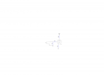
You haven't said what if anything is connected to the input, but in most applications there should be a blocking capacitor at the input to ensure that the signal source cannot upset the tube bias by applying DC at the input. Your circuit should look something like the attached.
You haven't said what if anything is connected to the input, but in most applications there should be a blocking capacitor at the input to ensure that the signal source cannot upset the tube bias by applying DC at the input. Your circuit should look something like the attached.
Attachments

Bit late to the game here. Jerryamp, what is the DC input resistance of the meter you are using? It could be pulling down your readings of the grid voltage.
Cheers
Matt.
Cheers
Matt.
Hi Matt,
Oh! Actually I don't know.. It's a fairly basic one (UZ82D) I can't find the specs.. I can attempt to measure it using a resistor and a battery I believe.
**EDIT** It says on the meter 2kOhm /V... That's the sensitivity correct? Is that the same thing?
Oh! Actually I don't know.. It's a fairly basic one (UZ82D) I can't find the specs.. I can attempt to measure it using a resistor and a battery I believe.
**EDIT** It says on the meter 2kOhm /V... That's the sensitivity correct? Is that the same thing?
Last edited:
It's more important to measure the voltage at the grid, referenced to ground. This should be zero volts regardless of the input impedance of your meter.
Is it the analogue meter Maplin used to sell when they were about? Real shame they have gone.
Anyway, with an analogue meter like that you will get low readings at such high impedance points as the grid of an input stage.
Cheers
Matt.
Anyway, with an analogue meter like that you will get low readings at such high impedance points as the grid of an input stage.
Cheers
Matt.
Oh! So actually my bias could be OK? Oh my...
So as Ray mentioned.. If grid to ground is zero and voltage across the cathode resistor is correct I should be OK?
Can I get a meter that would give me an accurate reading without breaking my bank account? A basic digital one?
Thanks guys... I'll get there I hope!
So as Ray mentioned.. If grid to ground is zero and voltage across the cathode resistor is correct I should be OK?
Can I get a meter that would give me an accurate reading without breaking my bank account? A basic digital one?
Thanks guys... I'll get there I hope!
Yes it looks fine, sorry just had that feeling you were using a moving coil meter. Had to say something. I use an old AVO a lot as the movement of the meter can tell you loads. Always good to have an analogue meter.
Plenty of decent digital meters about. Even the cheapest have a 10Meg input resistance. Go with what you can afford.
Cheers
Matt.
Plenty of decent digital meters about. Even the cheapest have a 10Meg input resistance. Go with what you can afford.
Cheers
Matt.
Oh! So actually my bias could be OK? Oh my...
So as Ray mentioned.. If grid to ground is zero and voltage across the cathode resistor is correct I should be OK?
You haven't actually said what the grid-to-ground voltage is; you've only reported that the cathode-to-ground voltage is 1.6 volts. The bias on the tube will be the difference between these two voltages, so if the grid is in fact at zero volts (relative to ground) then you are probably OK. Read the voltage at the grid and let us know what that is. If it is something other than zero then you need to find out where that DC voltage is coming from.
For a Guitar amplifier, a 68k grid stopper makes sense.
The gain in circuit of the 12AX7, the Miller Effect Capacitance, and the 68k grid stopper makes a great Low Pass Filter.
Great for a Guitar amp!
68k grid stopper is Not good for Hi Fi.
The gain in circuit of the 12AX7, the Miller Effect Capacitance, and the 68k grid stopper makes a great Low Pass Filter.
Great for a Guitar amp!
68k grid stopper is Not good for Hi Fi.
Ray, with his nominally 2K input on the lowest range of the meter he will always read 0V between grid and ground. An extreme case would be a 1 ohm input resistance meter. Ideal for measuring current? The input resistance of the meter is in parallel to the grid to ground resistance. It swamps the value of the grid to ground resistor and so the reading is not true.
Cheers
Matt.
Cheers
Matt.
An easy way to find out if the grid has any voltage on it.
1. Disconnect everything that is before the input capacitor and 1 Meg grid resistor.
Measure the cathode voltage.
2. Short the grid to ground.
Measure the cathode voltage.
Any difference in voltage from 1 to 2 is the open circuit grid voltage.
Done!
1. Disconnect everything that is before the input capacitor and 1 Meg grid resistor.
Measure the cathode voltage.
2. Short the grid to ground.
Measure the cathode voltage.
Any difference in voltage from 1 to 2 is the open circuit grid voltage.
Done!
Ray, with his nominally 2K input on the lowest range of the meter he will always read 0V between grid and ground. An extreme case would be a 1 ohm input resistance meter. Ideal for measuring current? The input resistance of the meter is in parallel to the grid to ground resistance. It swamps the value of the grid to ground resistor and so the reading is not true.
I was commenting on the 1.6 volt cathode-to-ground reading and the reported -0.8 volt grid-to-cathode reading (see post #26). This implies a grid-to-ground voltage of +0.8 volts, not zero. So the readings presented were confusing (to me at least).
But it looks like jerryamp has sorted this out for himself.
...It says on the meter 2kOhm /V...
That is incredibly low for any tube circuit, especially skinny bottles like 12AX7. Put it in your truck for testing the battery or trailer lights.
Up until 1950 it was not uncommon for commercial schematics to note "Measured with 20K/V meter". (The good Simpsons and AVOs.) By 1960 11Meg VTVMs were common (Thanks, HeathKit!) and we knew to expect marginally higher readings than old schematics showed.
IMHO the VTVM is still king for vacuum tube work, but passable DMMs are very very affordable now. Most are 10Me, but a few (particularly for electrician use) are 1Meg.
PRR,
Agreed.
If all he has is a 2k/Volt meter, then put the meter on the 10V scale (20k Ohms).
Very carefully read the meter (account for parallax by keeping the eye directly over the needle, and carefully interpolate between the meter marks).
The meter will affect the voltage across the 12AX7 2.2k self bias resistor by about 11%. Without the meter on the circuit, the voltage will be 11% higher than the reading.
If the 12AX7 is gassy, a 1Meg Rg will affect the bias.
Read the cathode volts with the 1Meg in place.
Read the cathode volts with a short across the 1Meg.
Any difference in those two readings is caused by grid current.
The best measurement tools are not always available.
But know the test equipment. Know the circuit that is being tested.
Calculate and compensate as needed.
I learned that lesson on a US Naval Destroyer in the middle of the Pacific Ocean.
- Home
- Amplifiers
- Tubes / Valves
- basic question on plate curves