Hi im intrested in creating a simple unity gain buffer
that i could use with or without an input capacitor (preferably id use a switch) to isolate the output capacitors/filters of source devices with the input filters/potentiometer of the amplifier, id also like to use an virtual ground circuit to simplify power delivery, im not intrested in tone control or anything like that.
that i could use with or without an input capacitor (preferably id use a switch) to isolate the output capacitors/filters of source devices with the input filters/potentiometer of the amplifier, id also like to use an virtual ground circuit to simplify power delivery, im not intrested in tone control or anything like that.
Hi, is this what you are looking for?
Polarity of 10uF caps in the dual power supply option will depend if your input/output have DC component.
If not, you can use as described.
220uF/47k is a ripple filter on the single power supply option and depends on how much ripple your power supply will have.
10uF at the output will depend on the minimum frequency response you need and the input impedance of the equipment to drive.
To drive 10k impedance with 10uF you will have response starting at around 2Hz.
10uF/47k at input is just a suggestion and depends on what you need as input impedance and minimum frequency response.
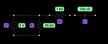
The thing is that sources often have an output capacitor that parallels and creates weird filters like this.
This is what i found at the output of one of these cheap toslink to rca dac,s it didnt play nicely with my amplifier and all of the bass was gone.
This is what i found at the output of one of these cheap toslink to rca dac,s it didnt play nicely with my amplifier and all of the bass was gone.
Attachments
Sure! 100nF is to small to couple with audio input impedance standards (10kohms, 47kohms). So, just replace it by a larger one.
I normally calculate coupling caps to start at least at some Hz so as to be flat between 20-20kHz.
I normally calculate coupling caps to start at least at some Hz so as to be flat between 20-20kHz.
thats an issue with the dacSure! 100nF is to small to couple with audio input impedance standards (10kohms, 47kohms). So, just replace it by a larger one.
I normally calculate coupling caps to start at least at some Hz so as to be flat between 20-20kHz.
what about this? provides an clear input for devices with or without an input capacitor (preferably controlled with a switch)
It is not unity gain 🙂
R4 is not needed.
The input needs configuring correctly. It only works in simulation because the input voltage source is ground referencing the opamp input. Use a coupling cap and input bias resistor. 0.22uF and 470k is fine if the opamp is a FET device like a TL071 etc.
Also you r 24 volt power supply in a real build would have to be floating (no ground reference) or else you would have to configure the opamp for single rail.
sources are weird as i said so id like an purely capacitor free input stage, R4 represents an input impedance, and the amount of gain here is ideal to turn an eu line level to an us line level (500mV to 1V)
Hi NO ideas. If you want a buffer to build a pre-amp, I'd say check out the B1 from Nelson Pass. It's pretty great. https://www.passdiy.com/store
The B1R2 is even better IMHO. It's a DC coupled balanced version but he has no kit for it that I know of.
So... I made one that can be populated as a B1R2 buffer only, an opamp with gain stage only or both together. You can go pricey or inexpensive, with or without gain and it all sounds good no matter the choice is.
I made a few versions, one with regulation built in, one with rectifiers and regulation built in. Both have an Alps RK27 pot on baord for level control
Here is a picture of the one with regulation only being used as a pramp with Pearl 3 phon boards. It all works well.
I have extra boards tyhat would love to find a good home. PM me if you want one.
Cheers.

I thought you just wanted to recommend me the pass kit to buy or something sorry for being rude and this misunderstanding.No ideas -- Did I mention money? I was offering for free! I would have picked up the postage as well. I'm all about sharing. This is a group of pretty generous helpful people here. Oh well.... I'm sure you'll figure something out.
Whoops, this is a very bad idea:

While the SW?A switches the opamp has no bias current and will smash to the rail, probably propelling your speaker cones across the room!! Also if no input is plugged in and the top path is selected the same thing happens.
If you want DC/AC switching just put the switch across the capacitor!!
While the SW?A switches the opamp has no bias current and will smash to the rail, probably propelling your speaker cones across the room!! Also if no input is plugged in and the top path is selected the same thing happens.
If you want DC/AC switching just put the switch across the capacitor!!
sources are weird as i said so id like an purely capacitor free input stage, R4 represents an input impedance, and the amount of gain here is ideal to turn an eu line level to an us line level (500mV to 1V)
R4 is just a very high value load on the opamp and plays no part in input characteristics.
In your later circuit you need R1 and R2 permanently connected to the opamp input to provide correct DC bias whether or not the input floats or is connected to a capacitor coupled output stage feeding the buffer.
The 5532 is about as bad as it gets for highish input bias currents (which will give a DC offset at the output). 47k input loading is much lower than it needs to be.
Use a different opamp for DC coupling and increase R1 and R2 by a factor of 10 and reduce the coupling cap by the same factor.
- Home
- Source & Line
- Analog Line Level
- basic preamplifier/unity gain buffer