I bought a Gustard p26 preamp and plan to swap op amps. The problem is, after removing a few screws that appeared to be securing the top, it won't budge. I'm assuming the top aluminum plate is snapped in, but I see no way of getting a tool in to pop it out. I don't want to scratch it up by forcing a knife or screwdriver in. Is there a trick to this? Help.
Just thinking aloud: there might be tongue-in-groove fasteners grabbing in those rectangular slots, needing sideways movement: cover first moves sideways (say 10 mm), unsnaps, and then can be pulled up.
The round spring loaded silver button fits in a round hole in cover, and must be pushed down (with a pencil tip) to allow lateral movement.
As usual, "reading" 10 pages out of fragments of one. 🙄 🙄 🙄
As a side note: if the goal is "roll Op Amps to improve design", forget it.
Unit is clearly very well made and designed, highest class, you will NOT outsmart the designer.
Forget anything you "read in Forums" 🙄
Waste of time.

The pictures do not show any screw in he top.
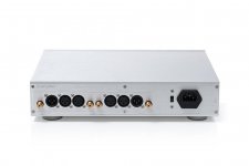
I suggest you remove the front knob, then the 6 screws in the back around the perimeter and finally try to pull gently the back to see if it slides out of the cabinet.
That is the way many devices are assembled.
I hope it helps.
I suggest you remove the front knob, then the 6 screws in the back around the perimeter and finally try to pull gently the back to see if it slides out of the cabinet.
That is the way many devices are assembled.
I hope it helps.
The designer put in opamp SOCKETS, so in this particular case I would plead entrapment.you will NOT outsmart the designer.
And a final scare........The designer put in opamp SOCKETS, so in this particular case I would plead entrapment.
Does Designer encourage or even suggest OP Amp rolling?The designer put in opamp SOCKETS, so in this particular case I would plead entrapment.
Very much doubt so.
For the entrapment plea: user should prove those were prominently displayed, in order to bait him.
So, in your view, HOW could user even see them, as assembled, and given the warning wiseoldtech shows?
JMF, that warning label is just a .jpg photo that I have saved, mostly for humorous reasons, (notice my avatar) and on occasion to print up as labels to put on some products - normally for equipment that I've restored/repaired for customers for their own safety.Does Designer encourage or even suggest OP Amp rolling?
Very much doubt so.
For the entrapment plea: user should prove those were prominently displayed, in order to bait him.
So, in your view, HOW could user even see them, as assembled, and given the warning wiseoldtech shows?
EVEN THOUGH it's usually ignored anyway by many!
As for someone wanting to putz around and start changing perfectly good IC's just because of the fact of the matter is that they're in 'sockets', some op amps are known to react to being in sockets, and break into oscillation or instability if certain measures and/or precautions are not followed.
What amuses me is that the common DIY'er takes on a 'tinkering around' project driven by some self-proclaimed internet guru, also of questionable authority, and like sheep attempts to 'improve' something that is perfectly fine.
Then threads appear, asking 'what did I do wrong?' - and they go on forever.
I've noticed this on several different audio and video websites, not just on here.
Yeah, ok, so you bought a radio shack multimeter at the flea market, along with a bargain price $4.00 used soldering iron, and you're technical Bible is the laptop tuned into the internet, and now you're prepared to be a full-fledged master technician on your kitchen table.
You're convinced that you can accomplish something wonderful, amazing, beyond and better than what a crew of professionally trained designers/engineers have already produced and thoroughly tested in a laboratory for commercial use.
Don't get me wrong, in some instances, a bit of modification does help with some products, due to cost-cutting, and lord knows the current cheapening and lack of longevity of some newer devices.
But attempting to reach some 'holy grail' performance out of something is not always a good idea. 😉
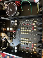
I also think the screws on the little switch on the back and the XLR connector screws may need to come off. From Rayma's internal photo the XLR's look to be soldered onto the main board, so they do not come off with the back. I'd start with the six on back and then if it doesn't wiggle, remove the others. If the top wraps around to the bottom, the screws holding the top cover may be on the bottom. There are just not enough photos to get a good feel for how the box is put together.The pictures do not show any screw in he top.
I suggest you remove the front knob, then the 6 screws in the back around the perimeter and finally try to pull gently the back to see if it slides out of the cabinet.
That is the way many devices are assembled.
I hope it helps.
All this sticker means to me is it's solid state LOL
And it's horses*it anyway. I was more of a user than a "qualified service personnel" when I was a kid and started messing around with the stuff anyway and I fixed plenty of stuff. Never got a shock off of anything, either and that includes running CRT monitors with no casing.
Of course it's really about being sued.
As an aside:
I was "scared" into respecting electric when I was a kid.
My father came into the garage to see me attempting to stick something into the receptacle.
He said "Don't do that! 10,000 Volts will fly out of the wall at you!" but I had never heard the word Volt before, so I thought he said bolts... I literally pictured 10,000 pieces of hardware flying out of the wall!
How did you take that pic without removing the top?Here's one photo if it helps.
.................
What amuses me is that the common DIY'er takes on a 'tinkering around' project driven by some self-proclaimed internet guru, also of questionable authority, and like sheep attempts to 'improve' something that is perfectly fine.
Then threads appear, asking 'what did I do wrong?' - and they go on forever. 😉
I've noticed this on several different audio and video websites, not just on here.
Yeah, ok, so you bought a radio shack multimeter at the flea market, along with a bargain price $4.00 used soldering iron, and your technical Bible is the laptop tuned into the internet, and now you're prepared to be a full-fledged master technician on your kitchen table.
You're convinced that you can accomplish something wonderful, amazing, beyond and better than what a crew of professionally trained designers/engineers have already produced and thoroughly tested in a laboratory for commercial use.
.......
Fine if it has some base supporting it.attempting to reach some 'holy grail' performance out of something is not always a good idea. 😉
But I see many itch to "do/design/improve" stuff , which is fine, a perfectly valid goal, BUT it usually takes STUDYING, and that does not mean a 5 minute YT video but real book reading, taking whatever time it takes to understand, do the exercises included if anything, leave aside for a week or two and then reread it ...you always "click" to something new.
If what you just learnt can be bench tested, with real world components, (usually quirky and different from idealizations), even better.
But the noob/tyro does not have the disposition or patience or, frankly, skills, so takes "the easy way out"Avoiding even the most basic of basics, say Ohm´s Law, parallel/series association of components, or basic RC cutoff frequency calculation , their "design/improvement" level is to replace some perfectly working component by another, hopefully same value, but imbued with magical properties, there´s no other word to say it.
So replacing a cathode capacitor by another, same value but costing 50X more now "improves soundstage", "makes female vocals present" and "covers everything in honey like sweetness"
REALLY??????
he doesn´t say HE took it.How did you take that pic without removing the top?
Most probably found in the Net.
Of course, helpful, if it belongs to same model .... of which I am not too sure.
Yesterday after you complained, Rayma baited all of us with that picture showing the sockets.For the entrapment plea: user should prove those were prominently displayed, in order to bait him.
So, in your view, HOW could user even see them, as assembled
Really now, in 2022, the question should be where are you going to get a half-decent opamp to fit those huge sockets?
Attachments

Bingo!If what you just learnt can be bench tested, with real world components, (usually quirky and different from idealizations), even better.
But the noob/tyro does not have the disposition or patience or, frankly, skills, so takes "the easy way out"Avoiding even the most basic of basics, say Ohm´s Law, parallel/series association of components, or basic RC cutoff frequency calculation , their "design/improvement" level is to replace some perfectly working component by another, hopefully same value, but imbued with magical properties, there´s no other word to say it.
So replacing a cathode capacitor by another, same value but costing 50X more now "improves soundstage", "makes female vocals present" and "covers everything in honey like sweetness"
REALLY??????
People often want to 'put the carriage before the horse' and take an easy path these days.
It's become a button-pushing, screen-tapping society where everything's convenient.
Who the heck needs Ohm's Laws, resistor Color Codes, or any of that other boring crap?
The internet, with its vast worldy information and its plethora of guru's will help me if I get into trouble.
No need to bother with getting a degree, much less understanding dribble-drabble technical talk, I'm only playing around, right?
- Home
- Amplifiers
- Solid State
- Basic help needed to open a case